Simulation stages of digital signal processing with LTSpice, and compiler C
This document focuses on showing the occurrence of processes at each stage and integration of those processes, not discussing system optimization or subsystem.
Preparation
- Install LTSpice
- Install JDK for Netbeans 8.2
- Install Netbeans 8.2 for the C compiler IDE
- Install Cygwin and the GCC compiler in Cygwin
- Install Python 3. x
- Install the SciPy library to convert WAV file
- Install Arduino IDE for compiling code ATmega328
- Install Audacity to view WAV file contents
- Download/Clone Repository https://github.com/waskita/embedded
Process simulation
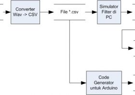
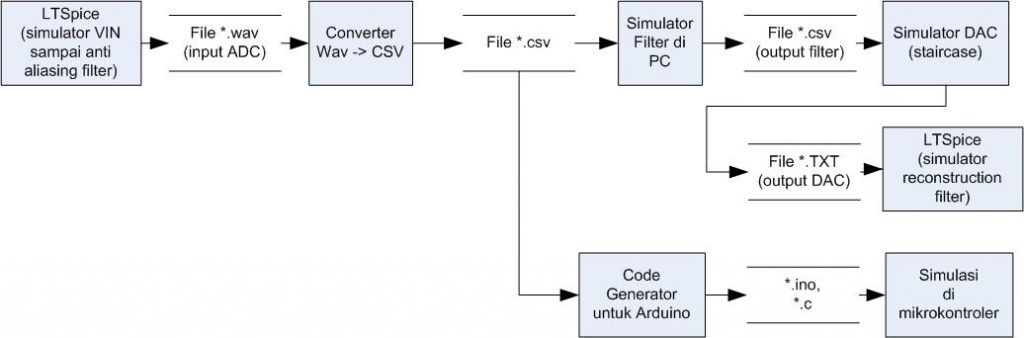
The process of signal flow on the complete digital signal processing is as follows (source):
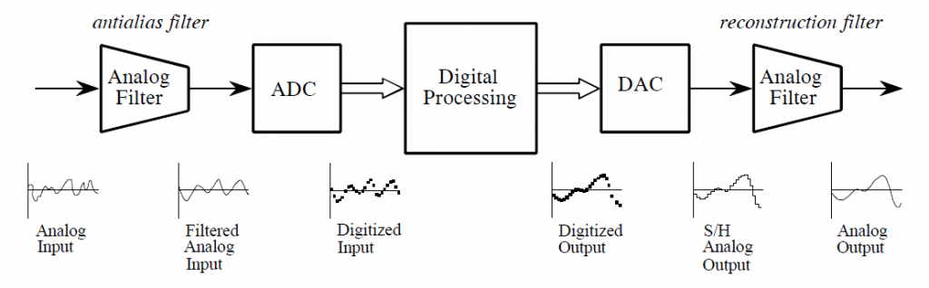
Here is a signal diagram to be simulated

Brief simulation Stage:
- AC Input and analog circuit simulated with LTSPice
- Quantization in ADC simulated with program C
- Digital Filter simulated with C language program
- DAC simulated with C language program
- Reconstruction filters simulated with LTSpice
Simulation This is only to show the framework for conducting simulations Digital filter, it is done simplification as follows
- Filter Anti aliasing using RC Order 1 filter, without calculating the value Cut-off frequency. In the task must be observed frequency cut off, Order Filters and Filter types
- The reconstruction filter uses the RC Order 1 filter, without calculating the cut-off frequency value.
- Digital filters use moving averages with 3 digits. Should use LPF, HPF BPF, BSF as needed.
- Only Counting response at 1 frequency. The response should be measured Multiple frequencies to get the response curve of the A/Bode plot.
Output WAV at LTSpice has limitations that only have a level Voltage-1 Volt to + 1 volt, so for subsystems that have Input/output exceeds the range must be adjusted, or The simulation is done only at a range of-1 to + 1 volt.
Detailed simulation Stage
Simulation on Desktop Computers
Create the front analog circuit simulation including the voltage source AC, LPF, shift level, amplifier and so on. This block Output will enter To ADC, so it should be that the level of the voltage is ADC input voltage. ATmega328 can be set reference at 2.56 volts or VCC. In practice, VCC is less stable, better wear Internal or external references.
Sample simulation file: Anti-aliasing-filter. ASC
Here are examples of air conditioning signal source network and anti aliasing filter:
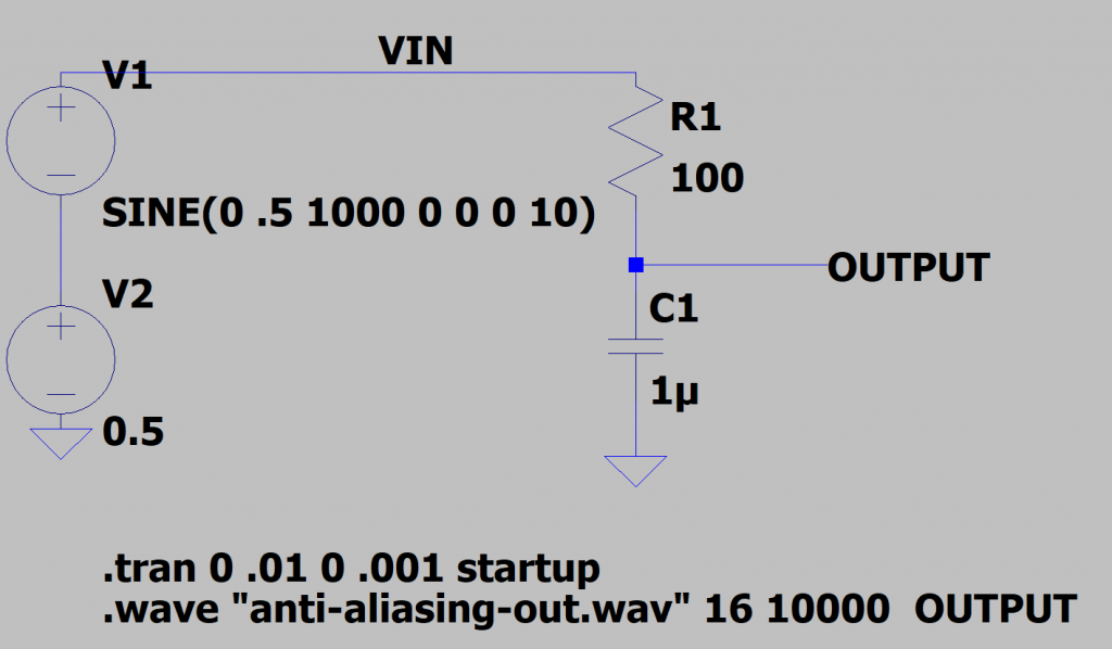
Select the input frequency (e.g. 1000 Hz)
Add WAV output, example syntax: ‘ “. Wave” anti-aliasing-out. WAV “16 10000 OUTPUT” ‘
- 16: Bitrate The amount of bits, anything because it will be cut off at quantization time
- 10000: Sampling frequency 10 kHz
- VIN: A label named Winyal WAV (Channel 1)
- OUTPUT: The name of the label to be WAV signal (Channel 2)
Sampling rate is likened to the sampling frequency of the software (e.g. 10 kHz)
A large Bitrate (e.g. 16 bits) can be rounded up in the C program. Reality is later rounded up to the number of bits on the ADC (10 bits on ATmega328)
Here are V (VIN) and V (output) views. NampakV (output) is slightly muted and shifts the phase slightly.
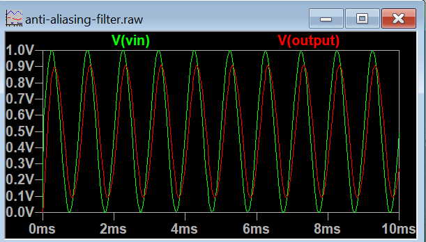
Supposedly the V signal (output) is already within the voltage limit of 0 to VREF. The V (output) signal is not yet suitable for inclusion in ADC due to ADC On ATmega328 only accept signals with a voltage of 0 volt until VREF.
The simulation on the above LTSPice produces the output time series in WAV format.
Perisai outputs the output in a WAV file with a program that can display WAV files (e.g. Audacity https://www.audacityteam.org/), making sure that the resulting WAV signal is ‘ sensible ‘.
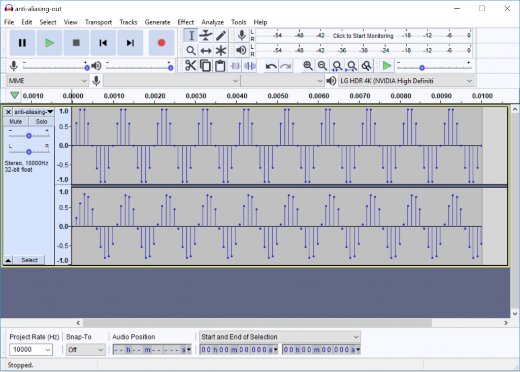
Here is an example of WAV file (anti-aliasing-out. WAV) with Audacity:
The next WAV file is converted to CSV so it’s easy to read by the filter simulator program. If there is a library, it can also be directly read WAV file with the filter simulator program.
Example converter: https://github.com/Lukious/wav-to-csv, changed slightly to wav2csv.py script in the repository. Install python, scipy and Panda to be able to run wav2csv.py
Anti-aliasing-out. wav File is converted to anti-aliasing-out. csv
Check the contents of the CSV file, can be viewed with Excel to see if the result is appropriate.
Here is an example of a viewed CSV file in Excel: (Anti-aliasing-out. xlsx)
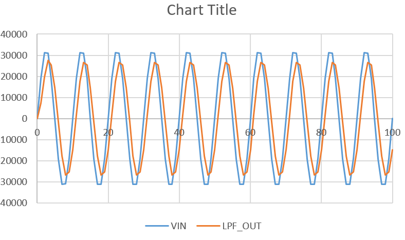
Next Run the Digital filter simulator program (Simulated-filter/Main. c). The Program reads the CSV file, then data Time series is inserted into the filter_moving_average function. Output written To a text file in CSV format (“simulated-filter. CSV”).
Adc Be simulated by conducting LPF_OUT signal quantization of a number of Resolution of the used ADC. ATmega328 has a resolution of 10 bits, so LPF_OUT signal must be quantized into numbers 0 to 1023 (1024 Level).
Examples of digital filter simulation software can be viewed at https://github.com/waskita/embedded/tree/master/simulasi-filter-digital/simulasi-filter. The Proram was written with the Integrated Development Environment (IDE) with Netbeans 8.2), compiler C with Cygwin.
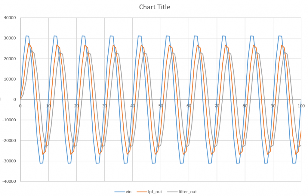
To Be compared between the output signals of the generator Signals, signal entry to ADC, and digital filter result signals.
Following VIN charts, LPF_OUT and FILTER_OUT (simulation-FILTER. xlsx)
The next stage is to create a DAC output signal in WAV format and then simulate reconstruction filter with LTSpice.
The Output DAC is in the form of a of order hold, such as the following: (source)
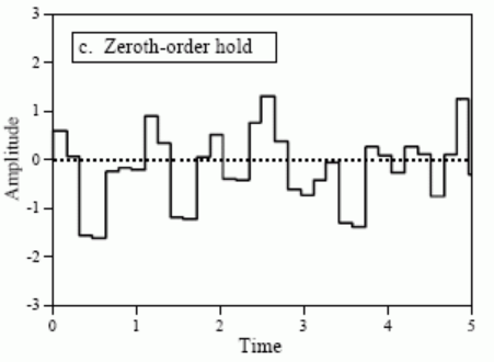
To generate a of order hold signal, it is necessary to do the following
- Do Quantization of output according to the resolution of the used DAC. On the system This used DAC MCP4725 has a resolution of 12 bits. If used ESP32, Then it must use 8 bit resolution.
- Increase sampling rate, For simulation of its occurrence in the form of stairs. E.g. by raising so 10x the current sampling signal to 100 Khz.
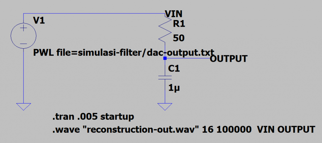
LTSpice can receive WAV and TXT inputs. On Simulation reconstruction filters are used TXT only so as not to Do the CSV to WAV conversion. This procedure is described in the video Following (https://www.analog.com/en/education/education-library/videos/5579265677001.html), and at https://www.analog.com/en/technical-articles/ltspice-importing-exporting-pwl-data.html
Here’s an example of a simple reconstruction filter set (reconstruction-Filter. ASC)
Here’s the output DAC and output reconstruction filter
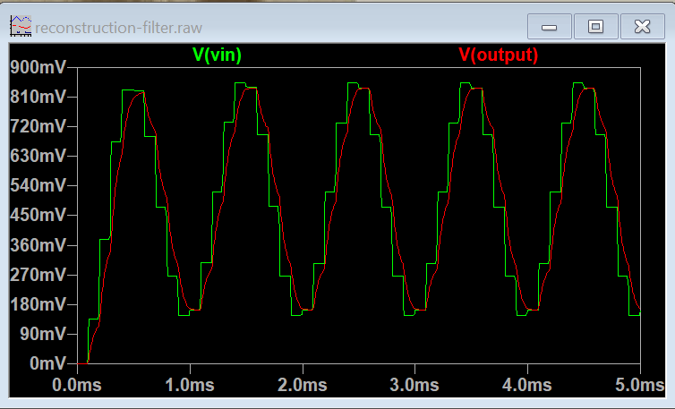
In the simulation above, it appears that the cut-off frequency is too high, so the ‘ ladder ‘ of the DAC output goes into the circuit output.
Simulation on Arduino ATmega328
The next step is testing the filter algorithm on the ATmega328 microcontroller (Arduino Nano).
Simulation is done with the following stages:
- Create an Arduino project to run the simulation. The project name is Atmega-simulation-Filter
- Source Code of digital filter function copied to Arduino source code
- The ADC output data is used as a const array in the data. h file. This process is done with the Arduino-createdata program
- Data. h File in-Include in the Arduino project
- Digital filter function is executed with data from the ADC output data array
- Output Filter result function sent to serial port
- Data From the serial port compared to simulated filter function results On desktop computers. There should be no difference Means.
Here’s the ADC output signal and the filter output from the Arduino serial output, plotted with Excel:
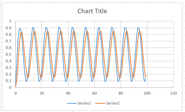
Filter result data on Arduino can be compared with filter result data on desktop computer
The next stage is filter speed testing[under construction]
Reference
- LTSpice https://www.analog.com/en/design-center/design-tools-and-calculators/ltspice-simulator.html
- Audacity
- Wav to CSV Converter: https://github.com/Lukious/wav-to-csv
- LTSpice Manual http://www.ieca-inc.com/images/LTSPICE_Manual.pdf
- LTSpice Manual https://ecee.colorado.edu/~mathys/ecen1400/pdf/scad3.pdf
- NetBeans 8.2 (https://netbeans.org/community/releases/82/
- Cygwin (https://www.cygwin.com/).
- DSP Guide: Digital to Analog Conversion http://www.dspguide.com/ch3/3.htm
- The Scientist and Engineer’s Guide to Digital Signal Processing http://www.dspguide.com
- DAC MCP4725 https://www.microchip.com/wwwproducts/en/MCP4725