HIS-07 Ionization Chamber of Ionization Smoke Detector
The single-source dual-chamber DSCB type ionization chamber designed according to the best performance of computer analogy is dedicated to smoke detectors. As the main component of the smoke detector, the ionization chamber fully complies with the American UL217 standard, the European EN-54-7 standard and the GB4715-93 national standard. The product quality is consistent, and the assembly of the detector does not need to measure the ionization chamber one by one, which is convenient for automated production
Working Principle
When the current of ionized electrons flowing through the inner and outer ionization chambers is unbalanced, the collector is charged until the ionization current reaches equilibrium. When there is no smoke or burning material, the collector keeps the equilibrium potential except for the statistical fluctuation of the ionization current. When smoke enters the ionization chamber, it affects the ionization current. The outer ionization chamber, which is easy to enter the smoke, is more affected than the inner ionization chamber. The ionization current drops, and the collector is recharged until the new equilibrium potential. This potential change can be used to trigger the alarm circuit
Feature
(1) Single-source double-chamber structure; small size, easy to install in a small alarm;
(2) Under the conditions of relative temperature and humidity of 40°C and 95%, the change value of the collected pole equilibrium potential is within the range of basic parameters;
( 3) The structure of the ionization chamber meets the requirements of UL217 Section 9.5 for anti-insect nets;
(4) Stainless steel and polyester materials and metal palladium on the surface of the ionization source have high corrosion resistance;
(5) The collector electrode has a good balance of potential uniformity and dispersion. Low degree, can be used for analog smoke detectors;
(6) All solder joints are pre-coated with solder to facilitate soldering and installation
Technical Specifications
Conditions:
- Voltage between the cover electrode and the source base electrode (working power supply voltage): 9 V
- Ambient temperature: 20±3°C
- Atmospheric pressure: close to standard atmospheric pressure, clean air
| Project | Numerical Value |
| Collector Balance Potential | .5±0.3 V |
| Collecting electrode potential varies with smoke concentration | |
| Dimming rate is 1%/ft | 0.6 V |
| The dimming rate is 4%/ft | 2.2V |
| Insulator leakage current (Max) | 0.5 pA |
| Capacitance (from collector to outer cover + to source base) | 6 pF |
,
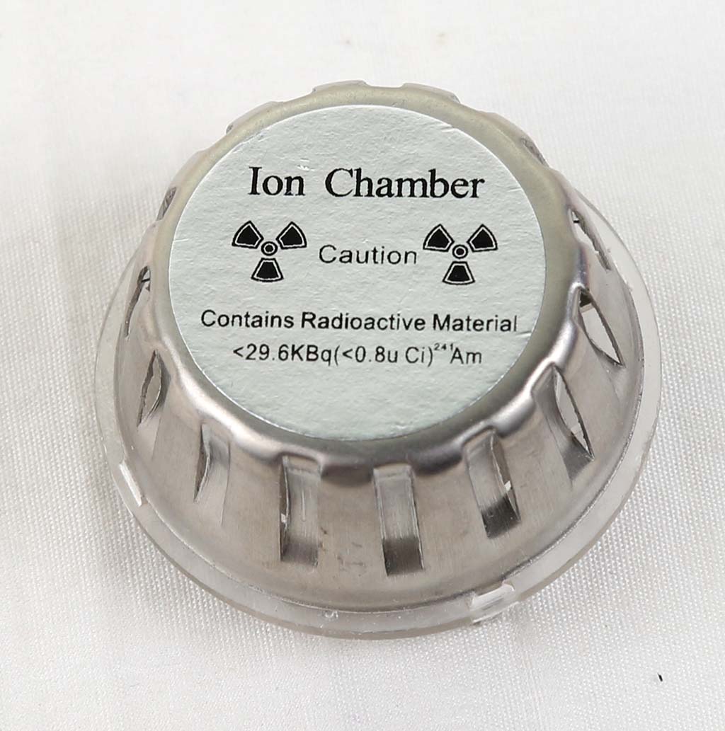
Ionization source characteristics and radiation safety performance
- Install a high-performance low-activity Am-241 ionization source in the ionization chamber
- Ionization source activity 0.5μCi(18kBq)±10% 0.8μCi(30kBq)±10%
- Ionization source alpha spectrum
- Peak: 4eV±10%
- FHWM (full width at half maximum): ﹤0.7 MeV
- Safety polarization standard (GB4075 ≈ ISO2919) C64444
- The radiation dose rate at 25cm of the ionization chamber is 0.03mGy/year (lower than 1mGy value of human population dose standard)
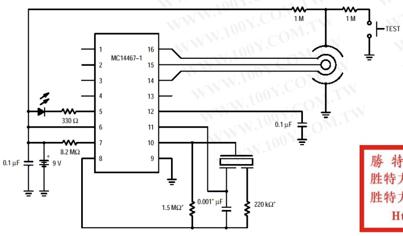
Recommended circuit diagram
If the smoke detector uses MC14467 components, please refer to the following circuit schematic diagram
Sensitivity characteristics
(According to UL217 standard wind speed 0.1M/sec)
|
Smoke concentration (%/ft)
|
The Output Voltage (V) | Error (ΔV) |
| 0 | 5.6±0.4 | 0 |
| 1 | 5.3±0.5 | 0.3±0.12 |
| 2 | 5.0±0.5 | 0.6±0.13 |
| 3 | 4.7±0.5 | 0.9±0.24 |
| 4 | 4.4±0.5 | 1.2±0.25 |
| 5 | 4.2±0.5 | 1.4±0.2 |
Power supply voltage characteristics (25°C.60%RH)
| Voltage | The output voltage (V) |
| 6 | 3.3±0.3 |
| 9 | 5.6±0.4 |
| 12 | 8.0±0.7 |
| 15 | 10.0±0.85 |
| 18 | 13.0±1.0 |
Temperature characteristics: (humidity: 60%)
Humidity characteristics (temperature: 25°C)
Shape and Structure
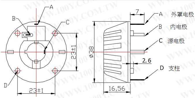
- A: Cover electrode: connect to positive electrode or power supply positive
- B: Inner electrode: output signal
- C: Source electrode: ground wire or power negative
- D: Pillar
Precaution:
1. To detect the output voltage, a meter or IC integrated circuit (MC14467/14468) with impedance above 1014NM is required. Ordinary instruments will cause inaccurate test results.
2. When assembling the smoke alarm, do not mistake solder and other sundries into the ion chamber of the device, otherwise it must be cleaned.
3. The output leads of the device should be connected in the air (Teflon support leads are generally used), because ordinary circuit boards will cause small leakage currents, which will make the test results inaccurate.
4. The device leads and the input leads of FETs and ICs need to be sealed with epoxy resin to minimize the leakage current caused by humidity.
5. Since the output current of the device is very small, the device needs a mask. Since the output current of the device is very small, the device needs a mask.
Ref