This demo will be created with a 1 timer interrupt on ATmega328 with a frequency of 1 kHz, and then performed the resulting frequency measurement.
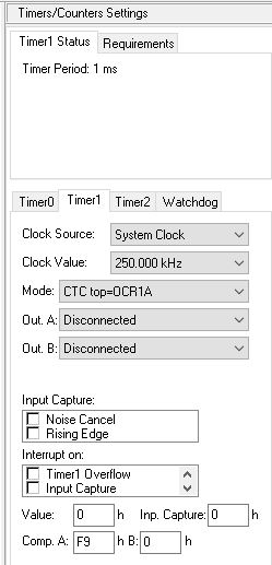
Configure Timer 1 as follows
- 1 kHz frequency, or 1 ms period
- Using Timer1
- Clock Source: System Clock
- Clock Value: 250 kHz (prescaler 64)
- Fashion: CTC top = OCR1A
- Out A: Disconnected
- Out B: Disconnected
- Interrupt on: Compare A Match
- No direct output to microcontroller pins
The clock frequency is 16 Mhz. With the 64 prescaler, the generated clock to Timer1 is 250 kHz. To create a frequency of 1 kHz, it needs a divider of 250 (0xFA), for which a number of 249 (0xF9) is required in the Register OCR1A. The timer1 Mode uses the CTC (Clear Timer on Compare), so when the counter number reaches 249, the next automatic becomes 0, coupled with the advent of the Timer interrupt 1. Thus the 1 250 kHz clock timer signal will generate a timer interrupt with a frequency of 1 kHz.
The code was created by using CodeWizard on the CodevisionAVR version of the Evaluation compiler. Here’s how the settings are set in the Code Wizard for Timer 1:
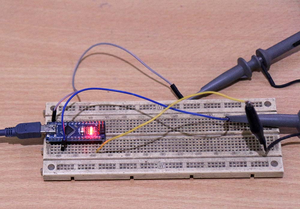
To generate the output signal, the C port is used as output. The Output on the C port is complementary to each interruption, so there will be a signal with a frequency of 500 Hz on port C. Here’s the ISR code (interrupt service routine) for the Timer 1:
interrupt [TIM1_COMPA]void timer1_compa_isr (void) {

P

ORTC = ~ PORTC

;}
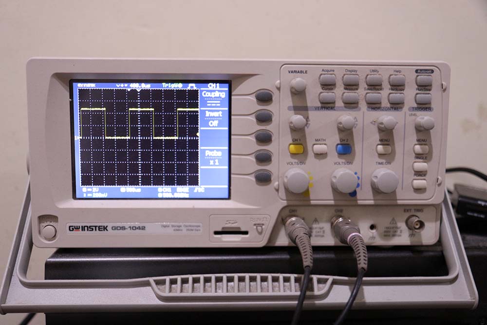
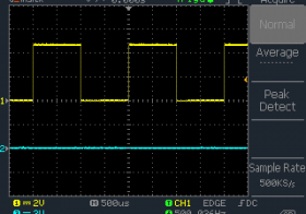
The following signals are generated, measured using an oscilloscope. The Screen capture is taken directly from the oscilloscope (not photographed).
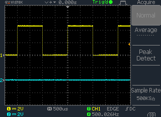
The measured frequency is 500.026 Hz, so the actual interrupt frequency is 2 x 500.026 = 1000.052 Hz. Not exactly as it should (1 kHz), the probability between an improper frequency of the crystals, or the clock on an improper oscilloscope.