Literatures on Finite State Machines

List of literatures on Finite State Machines

Scientific Papers

Articles

  • 2.3 Finite State Machine (FSM) Concept and Implementation https://web.stanford.edu/class/cs123/lectures/CS123_lec07_Finite_State_Machine.pdf
  • How to code finite state machines (FSMs) in C. A systematic approach https://www.researchgate.net/publication/273636602_How_to_code_finite_state_machines_FSMs_in_C_A_systematic_approach
  • State Machine Design in C https://www.codeproject.com/Articles/1275479/State-Machine-Design-in-C
    State Machine Design in C++ https://www.codeproject.com/Articles/1087619/State-Machine-Design-in-Cplusplus-2
  • https://robertolanuza.tripod.com/fsm/fsm.htm
  • Finite State Machines (FSM) in Embedded Systems (Part 1) – There’s a State in This Machine! https://www.embeddedrelated.com/showarticle/1625.php
  • System Design, Modeling, and Simulation using Ptolemy II: Finite State Machines
  • 7 – State Machines for Real-Time Embedded Systems from Part II – Real-Time Software Design Method https://www.cambridge.org/core/books/abs/realtime-software-design-for-embedded-systems/state-machines-for-realtime-embedded-systems/D00E3449C8C6EBB4FB5C3867AF35F7F2
  • Martin Gomez, Embedded State Machine Implementation, Embedded Systems Programming, 2000
  • Fernando Bevilacqua, Finite-State Machines: Theory and Implementation, 2013
    codes are in AS3 and Flash

Textbook

DRV8833 Motor Driver

Features

  • Dual-H-Bridge Current-Control Motor Driver
    • Can Drive Two DC Motors or One Stepper Motor
    • Low MOSFET ON-Resistance: HS + LS 360 mΩ
  • Output Current (at VM = 5 V, 25°C)
    • 1.5-A RMS, 2-A Peak per H-Bridge in PWP and RTY Package Options
    • 500-mA RMS, 2-A Peak per H-Bridge in PW Package Option
  • Outputs can be in Parallel for
    • 3-A RMS, 4-A Peak (PWP and RTY)
    • 1-A RMS, 4-A Peak (PW)
  • Wide Power Supply Voltage Range: 2.7 to 10.8 V
  • PWM Winding Current Regulation and Current Limiting
  • Thermally Enhanced Surface-Mount Packages

Description

The DRV8833 device provides a dual bridge motor driver solution for toys, printers, and other mechatronic applications.

The device has two H-bridge drivers, and can drive two DC brush motors, a bipolar stepper motor, solenoids, or other inductive loads.

The output driver block of each H-bridge consists of N-channel power MOSFETs configured as an H-bridge to drive the motor windings. Each H-bridge includes circuitry to regulate or limit the winding current.

Internal shutdown functions with a fault output pin are provided for overcurrent protection, short-circuit protection, undervoltage lockout, and overtemperature. A low-power sleep mode is also provided.
The DRV8833 is packaged in a 16-pin WQFN package with PowerPAD™ (Eco-friendly: RoHS & no
Limiting Sb/Br).

Reference

Supervisory Control Literature Survey

Literatures on Supervisory Control

Related Topics: Hybrid Systems

Tools

Course

R-2R DAC Getting Popular Over Delta-Sigma ADC

R-2R DACs and Delta-Sigma DACs are two popular types of digital-to-analog converters with distinct advantages and disadvantages.

Delta-Sigma DACs are more popular than R-2R DACs for a few reasons:

  1. Better performance: Delta-Sigma DACs can achieve higher resolution and lower distortion than R-2R DACs, making them better suited for applications that demand high accuracy and fidelity, such as high-end audio.

  2. Lower cost: Delta-Sigma DACs are widely used in consumer electronics, which has driven down the cost of manufacturing and made them more affordable than R-2R DACs in many cases.

  3. Lower power consumption: Delta-Sigma DACs typically consume less power than R-2R DACs, making them well-suited for battery-powered devices.

  4. Greater design flexibility: Delta-Sigma DACs offer greater design flexibility than R-2R DACs, as they can be implemented using a variety of architectures and can be optimized for different performance parameters depending on the application.

One of the key advantages of an R-2R DAC is its simplicity and linearity. R-2R DACs use a resistor network to convert digital data into analog signals, making them easy to design, manufacture and operate. This results in highly accurate, predictable and linear output signals, which are essential for applications such as audio, video, and measurement equipment. Additionally, R-2R DACs are relatively immune to jitter, noise and other digital signal distortions.

There are some recent improvement in R-2R technology such as  the Soekris Discrete R-2R Sign Magnitude Technology

R-2R DACs may be more popular in certain specialized applications, particularly those that require high linearity and accuracy, such as high-end audio equipment. R-2R DACs have a simpler architecture than Delta-Sigma DACs, which can result in better linearity and lower noise, making them better suited for such applications.

In summary, the advantage of R-2R DACs lies in their simplicity and linearity, while Delta-Sigma DACs excel in noise shaping and dynamic range. The choice between the two types of DACs ultimately depends on the specific application requirements and trade-offs between accuracy, speed, resolution, and cost.

What is R-2R DAC

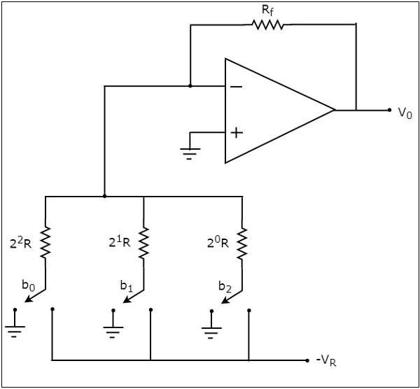
R-2R DAC (Digital-to-Analog Converter) is a type of DAC architecture that uses a network of resistors to convert digital signals into analog signals. It is named after the two types of resistors used in the network: “R” denotes the equal value resistors and “2R” denotes the double value resistors.

In an R-2R DAC, the input digital signal is first converted into binary format and then applied to the resistor network. Each bit of the digital signal is connected to an individual resistor. The values of these resistors are chosen in such a way that the voltage output at the end of the resistor network is proportional to the input digital signal. By adjusting the values of these resistors, the resolution of the DAC can be increased.

One advantage of R-2R DACs is their simplicity and linearity, which makes them well suited for high-performance audio applications. However, they can be more expensive and less power-efficient than other types of DACs, such as Delta-Sigma DACs.

Here is an example of simple 3 bit R-2R DAC circuit.

What is Delta Sigma DAC

Delta-Sigma DAC (Digital-to-Analog Converter) is a type of DAC architecture that uses a technique called delta-sigma modulation to convert digital signals into analog signals. This technique is based on oversampling the input signal at a high rate and then using a feedback loop to filter out the noise and reconstruct the analog signal.

In a delta-sigma DAC, the input digital signal is first oversampled at a very high frequency. The oversampled signal is then filtered using a digital filter that removes the noise and distortion. The resulting signal is then converted to an analog signal using a simple low-pass filter.

Delta-Sigma DACs offer several advantages over other types of DACs. They provide a high signal-to-noise ratio, which means that the output signal is very clean and free from noise and distortion. They are also very power-efficient, as they can be implemented using digital circuitry. However, they may be more complex and less linear than other types of DACs, such as R-2R DACs. Delta-Sigma DACs are commonly used in audio and digital communication systems, where high-quality output and low power consumption are critical.

Example of R-2R DAC

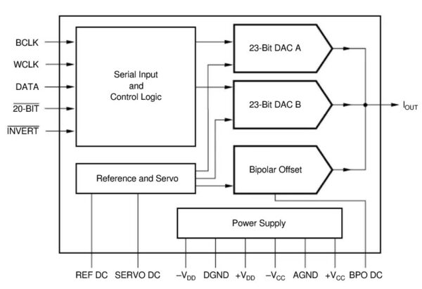
One example of an R-2R DAC that is commonly used in high-performance audio applications is the Burr-Brown PCM1704. This 24-bit DAC features a resistor ladder network that enables highly accurate and linear digital-to-analog conversion, making it well-suited for high-end audio applications. The PCM1704 has a dynamic range of over 120dB and a THD+N (total harmonic distortion plus noise) of -110dB, making it a popular choice among audiophiles and audio equipment manufacturers. The DAC is often used in high-end digital-to-analog converters, preamplifiers, and other audio equipment where accuracy and linearity are critical.

Block diagram of PCM1704 DAC

PCM1704 is already obsolete. For new products, we can use other DAC such as DACx1001 from Texas Instruments

R-2R DAC is used in some high-end audio devices, such as SE300 from Astell & Kern.

Also  Hiby RS8

Example of Delta Sigma DAC

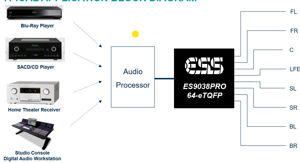
One example of a Delta-Sigma DAC that is commonly used in high-performance audio applications is the ESS Sabre ES9038PRO. This 32-bit DAC uses a multi-bit Delta-Sigma architecture that enables high-precision digital-to-analog conversion with very low noise and distortion. The ES9038PRO is designed for use in high-end audio equipment and has a dynamic range of 140dB and a THD+N of -122dB, making it one of the best performing Delta-Sigma DACs on the market. The DAC is often used in high-end digital-to-analog converters, headphones amplifiers, and other audio equipment where high resolution and low noise are critical.

Here is a typical usage of ESS ES9038PRO

References


Advantages of FPGAs Over Microprocessors

FPGAs (Field Programmable Gate Arrays) and microprocessors are both types of digital electronic components, but they have different architectures and are suited to different types of applications. Here are some advantages of FPGAs over microprocessors:

  1. Parallel Processing: FPGAs are designed to perform multiple operations in parallel, which makes them faster than microprocessors for certain types of applications. While microprocessors execute instructions sequentially, FPGAs can perform many operations simultaneously, which is particularly useful for applications that require high-speed data processing or real-time signal processing.

  2. Customizability: FPGAs are highly customizable, allowing users to design custom logic circuits and interfaces for specific applications. In contrast, microprocessors are designed for general-purpose computing and typically require additional hardware components to interface with specialized devices or sensors.

  3. Low Power Consumption: FPGAs can be designed to consume very low amounts of power, making them ideal for battery-powered applications or devices that need to operate in remote or inaccessible locations. Microprocessors, on the other hand, consume more power due to their sequential processing architecture.

  4. High Reliability: FPGAs are less susceptible to software bugs and security vulnerabilities than microprocessors, which can be vulnerable to viruses, malware, and other attacks. This is because FPGAs are configured using hardware descriptions, which are less prone to coding errors and other types of software-related issues.

  5. Real-Time Processing: FPGAs are designed for real-time processing applications, where data processing needs to be done in real-time without delays. Microprocessors, on the other hand, are not optimized for real-time processing and can experience delays due to the nature of their sequential processing architecture.

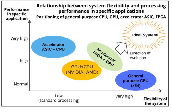
Relationship between system flexibility and processing performance in specific applications. Positioning of general purpose CPU, GPU, ASIC accelerators and FPGA. From https://hacarus.com/tech/20201207-amd-acquires-xilinx/

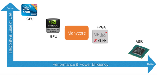
Comparison between flexibility and performance of CPU, GPU, FPGA dan ASIC. From: https://www.cs.cornell.edu/courses/cs6120/2022sp/blog/chlorophyll/

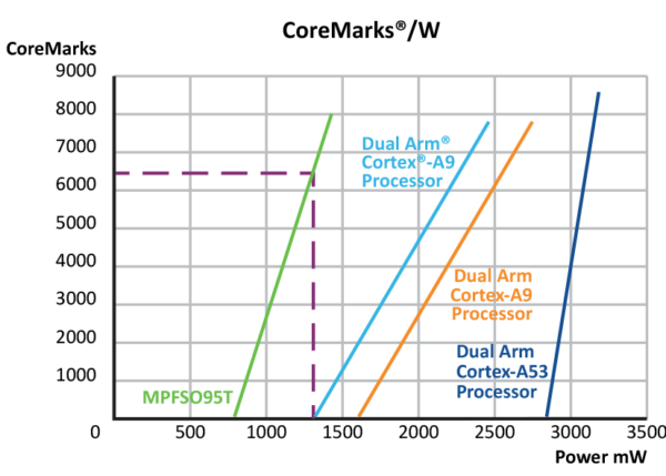
Illustration from “Lowest-Power Multi Core RISC-V SoC FPGAs“. Microchip has a comparison of its own microprocessors and FPGAs.

FPGA vs Arm Cortex-A9 vs Arm Cortex-A53

The EEMBC CoreMark-Pro benchmark graph clearly demonstrates the power-efficient nature of the PolarFire SoC FPGA. Leveraging the proven and renowned PolarFire FPGA architecture, the PolarFire SoC delivers exceptional performance with up to 50% lower power consumption than similar FPGAs. Remarkably, the PolarFire SoC FPGA consumes just 1.3W while delivering an impressive 6,500 CoreMarks, outperforming competing SoC FPGAs that deliver no CoreMarks. Moreover, at 8,000 CoreMarks, PolarFire SoC FPGAs consume 55% less power than competing FPGAs. The PolarFire SoC FPGA’s power efficiency combined with its exceptional performance, makes it a go-to choice for power-sensitive applications that demand high performance.

In summary, FPGAs are faster, highly customizable, consume less power, more reliable, and well suited for real-time processing applications compared to microprocessors. However, FPGAs are generally more expensive and require specialized knowledge and tools for programming and configuration. The choice between FPGA and microprocessor will depend on the specific requirements and constraints of the application.

References

Real Time System Without Real Time Operating System

Is it possible to build a real time system without using real time operating system (RTOS)?

Technically it is possible to build a real-time system without using a real-time operating system (RTOS), but it can be more challenging and requires careful design and implementation.

In a real-time system without an RTOS, the software is typically designed to use interrupts and timers to handle events and inputs with specific timing requirements. The code must be carefully structured and optimized to minimize processing time and ensure that critical tasks are executed on time.

There are some alternative to build a real-time system without RTOS include:

  • Cyclic executive. Cyclic executive is a simple scheduling technique that is suitable for small and relatively simple systems with fixed and predictable requirements. In a cyclic executive, tasks are scheduled to run in a fixed order, with each task being given a specific time slice in each cycle. Cyclic executives are easy to implement, but they have limited flexibility and scalability. They may not be suitable for larger or more complex systems with dynamic requirements or varying priorities.
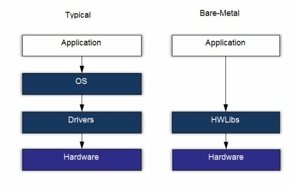
  • Bare-metal programming. This involves writing code directly for the microcontroller or processor without using an operating system. This approach can be fast and efficient, but it requires a deep understanding of the hardware and low-level programming skills.
  • Cooperative multitasking; In this approach, tasks are scheduled to run cooperatively, meaning that they voluntarily yield the processor to other tasks when they are done. Cooperative multitasking can be simpler than using an RTOS, but it may not be suitable for systems with strict timing requirements or tasks with different priorities.
  • Interrupt-driven programming; This approach uses interrupts to handle events and perform tasks, instead of relying on a scheduler. Interrupt-driven programming can be fast and efficient, but it may be more difficult to maintain and debug.

One approach is to use a bare-metal firmware, which is a minimal software layer that provides basic hardware abstraction and implements the real-time behavior directly in the code. Bare-metal firmware can be highly optimized for specific hardware and real-time requirements and can provide fast and predictable performance.

If a full RTOS is to big for our application, another approach is to use a small RTOS which is also known as lightweight real-time kernel or scheduler. Lightweight real-time kernel is a simplified version of an RTOS that provides basic scheduling and synchronization capabilities without the overhead of a full RTOS. Lightweight kernels can be easier to implement than full RTOSes and can be a good compromise between real-time capabilities and simplicity.

Some popular examples of lightweight real-time kernels include:

  1. FreeRTOS: FreeRTOS is a popular open-source LWKernel that is widely used in embedded systems. It provides a small set of kernel services, including task scheduling, synchronization primitives, and inter-task communication.

  2. uC/OS-II: uC/OS-II is a commercial LWKernel that provides a small set of real-time services, including task management, semaphores, and message queues. It is widely used in industrial and medical applications.

  3. ChibiOS/RT: ChibiOS/RT is an open-source LWKernel that is designed for small embedded systems. It provides a small set of kernel services, including task scheduling, synchronization primitives, and inter-task communication.

  4. RIOT: RIOT is an open-source LWKernel that is designed for low-power wireless embedded systems. It provides a small set of kernel services, including task scheduling, synchronization primitives, and inter-task communication.

FreeRTOS logo in green color
FreeRTOS logo

However, using an RTOS can provide many benefits in terms of ease of development, code reusability, and scalability. An RTOS can provide a standardized and well-tested framework for real-time system development and can make it easier to manage complex systems with many tasks and inputs. Ultimately, the choice of real-time system architecture depends on the specific requirements and constraints of the system being developed.

Glossary

  • Bare metal application is a firmware application intended to run without an operating system (OS)
  • A real-time system is a system that must respond to events or inputs within specific time constraints.
  • Operating Systems is a program that control the execution of application programs, and acts as an interface between applications and the computer hardware [Stallings, 2018]
  • A real-time operating system is any operating system that provides a deterministic way of executing a given piece of code. [Stallings, 2018]

References

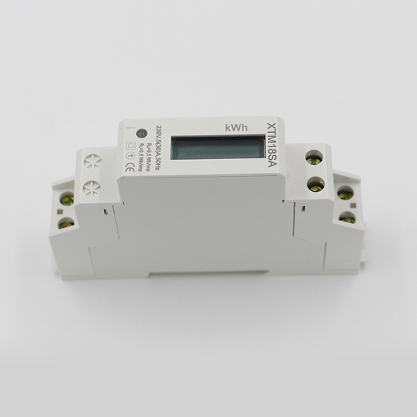
XTM18SA Single Phase DIN-rail Energy Meter


Description


Application                   XTM18SA

     XTM18SA is DIN rail single phase two wire active electronic energy meter. It adopts many advanced technologies of research and development, like microelectronic-techniques, specialized large-scale IC (integrated circuit), digital sampling and processing technology, SMT technique, and so on. The technical performances completely conform to International Standards IEC 62053-21 for Class 1 single phase active energy meter. It can directly and accurately measure the load active energy consumption in the single phase AC networks of rated frequency 50Hz or 60Hz. XTM18SA  has features with excellent long-term reliability, small volume, light weight, perfect appearance, easy installation, etc.This meter has already got the patent certificate from China State Intellectual Property Office at present. Patent certificate NO.ZL  2012 3 0473770.X, any other country patent certificate are in assessing.

Functions and features

  • XTM18SA series energy meters : Available as 35mm DIN standard rail mounted, conforming to Standards DIN EN 50022.
  • XTM18SA series energy meters : Single pole width (modulus 18mm), complying with Standards DIN43880.
  • XTM18SA series energy meters : Standard configuration 7+1 digits display (9999999.1kWh) without backlight LCD. May select 7+1 digits display (999999.1kWh) by white backlight LCD.
  • XTM18SA series energy meters : Standard configuration pulse output passive (polarity),May select distant pulse output passive (nonpolarity). And contact with all kind of AMR system conveniently,complying with standard IEC 62053-31 and DIN 43864.
  • XTM18SA series energy meters : Bicolor LED instructions power supply state (green) and signal of energy impulse (red).
  • XTM18SA series energy meters : Automatic detection the direction of the flow of load current. And Instructions on LED (when display HELP 1 on LCD, that means the reverse of the flow of load current).
  • XTM18SA series energy meters : Single direction measurement single phase two wire active energy consumption. It is nothing with direction of the flow of load current. Complying with standard IEC 62053-21.
  • XTM18SA series energy meters : Directly type S connection.
  • XTM18SA series energy meters : Extension terminals cover, in order to protect to use safety.

Technical parameters

* If you need different reference voltage or current specification, please advisory our sales.

Referensi

Jetson Nano 2GB Development Kit goes black after upgrading

Jetson Nano goes black after upgrading with ‘apt upgrade’. Graphical user interface is not working. Command line console still works.

Solution:

change window manager from lightdm

command:

dpkg-configure lightdm

Source

What is Integrated Circuit

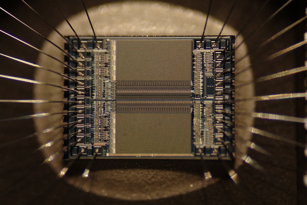
What is integrated circuit?

Answer: An integrated circuit (IC) is a circuit built on a single piece of semiconductor material, typically silicon, and containing a number of electronic components, such as transistors, diodes, resistors, capacitors, and inductors. The term is also used to refer to the physical device, the die, and the package that holds the die.

The name integrated circuit means that the circuit is “integrated” on one piece of semiconductor material, usually silicon. The circuit is made up of many tiny components called transistors, which are put together to make a complete circuit. The IC can also be made up of diodes, resistors, capacitors, inductors, and other components.

The term is also used to refer to the process of building the circuit, which is called integrated circuit fabrication.

[image source]

Origin

The term integrated circuit was coined in 1958 by Jack Kilby, who was awarded the Nobel Prize in Physics in 2000 for his work. The first integrated circuits were made of germanium, but silicon quickly became the material of choice.

Importance of Integrated Circuit

ICs are used in a wide variety of devices, including computers, cell phones, and other electronic equipment.

Electronic devices, such as computers, televisions, and smartphones, have many parts. Each part performs a different function. For example, a television has a power supply, a monitor, a tuner, a video processor, a sound processor, and a circuit to send signals to the television antenna.  A computer has a power supply, a motherboard, a CPU, memory, hard disk drive, video card, sound card, and many other parts. In order to make the television or computer work, all these parts have to work together.

Each part of the television or computer is connected to the other parts by wires. These wires are made of metal. If you look at the wires on the back of a computer, you can see that they are very thin. You can even see that they are made of several different colors of metal. The colors are used to identify the wires that are connected to the same part of the circuit. For example, all the red wires might be connected to the power supply, and all the green wires might be connected to the motherboard. The wires are usually very thin because the wires in the circuits of modern electronics are usually very thin.

Making Integrated Circuit

An integrated circuit is made from a silicon wafer. The wafer is made by slicing a large chunk of semiconductor grade silicon.

Thingsboard Rule Engine 2.0 Tutorials

Here are all Thingsboard Rule Engine 2.0 Tutorials:

List of all nodes in ThingsBoard v.3.4.0 and corresponding tutorial & guides for each node

Not all nodes are explained thoroughly. A few has no explanation. Most has short user guide. A few has long tutorial.

Node Name Related Article
Filter  
check alarm status  
check existence fields Filter Nodes
check relation

Check Relation between Entities

Filter Nodes

gps geofencing filter Filter Nodes
message type

Aggregate incoming data stream

Filter Nodes

message type switch
originator type

Aggregate incoming data stream

Filter Nodes

originator type switch Filter Nodes
script
switch Filter Nodes
Enrichment  
calculate delta Enrichment Nodes (PE)
customer attributes

Send Email to Customer

Enrichment Nodes (PE)

customer details Enrichment Nodes (PE)
originator attributes
originator fields Enrichment Nodes (PE)
originator telemetry

Telemetry delta calculation

Enrichment Nodes (PE)

related attributes

RPC Reply With data from Related Device

Send RPC Request to the Related Device

Enrichment Nodes (PE)

device attributes Enrichment Nodes (PE)
tenant attributes Enrichment Nodes (PE)
tenant details Enrichment Nodes (PE)
Transformation Transformation Nodes (User Guide)
change originator

Send RPC Request to the Related Device

Check Relation between Entities

Transformation Nodes (User Guide)

script
to email

Send email on alarm

Send Email to Customer

Transformation Nodes (User Guide)

Action  
assign to customer Action Nodes (User Guide)
clear alarm
copy to view Entity Views
create alarm
create relation Action Nodes (User Guide)
delay (deprecated) Action Nodes (User Guide)
delete relation Action Nodes (User Guide)
device profile  
generator
gps geofencing events Action Nodes (User Guide)
log

RPC Reply With data from Related Device

Action Nodes (User Guide)

message count  

push to edge

Action Nodes (User Guide)

push to cloud

Action Nodes (User Guide)
rpc call reply
rpc call request
save attributes
save timeseries
save to custom table Action Nodes (User Guide)
synchronization end  
synchronization start  
unassign from customer Action Nodes (User Guide)
External  
aws sns External Nodes
aws sqs External Nodes
azure iot hub External Nodes
gcp pubsub  
kafka External Nodes
mqtt External Nodes
rabbitmq External Nodes
rest api call

Notifications and Alarms on your smartphone using Telegram Bot

External Nodes

send email

Send email on alarm

Send Email to Customer

External Nodes

send sms  
Flow  
acknowledge Flow Nodes (PE)
checkpoint Flow Nodes (PE)
output Flow Nodes (PE)
rule chain

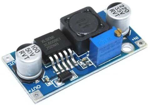
XL6009 DC-DC Step Up Boost Converter Module

400 kHz 60 volt 4 ampere switching current boost / buck-boost / inverting DC / DC converter

Features

  • Wide 5V to 32V input voltage range
  • Positive or negative output voltage programming with a single feedback pin
  • current mode control provides excellent transient response
  • 1.25 volt reference adjustable version
  • Fixed 400 kHz switching frequency
  • Maximum 4A switching current
  • SW PIN built in over voltage protection
  • excellent line and load regulation
  • EN PIN TTL shutdown capability
  • internal optimize power MOSFET
  • High efficiency up to 94%
  • Built in Frequency compensation
  • Built in soft-start function
  • Built in thermal shutdown function
  • Built in current limit function
  • Available in TO265-5L package

Applications

  • EPC / Notebook car adapter
  • Automotive and industrial boost / buck boost / inverting converters
  • Portable Electronic Equipment

General Description

The XL6009 regulator is a wide input range, current mode, DC/DC converter which is capable of generating either positive or negative output voltages. It can be configured as either a boost, flyback, SEPIC or inverting converter. The XL6009 built in N-channel power MOSFET and fixed frequency oscillator, current-mode architecture results in stable operation over a wide range of supply and output voltages.

The XL6009 regulator is special design for portable electronic applications.

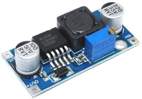
XL6009 module
XL6009 module


HIS-07 Ionization Chamber Smoke Detector Datasheet


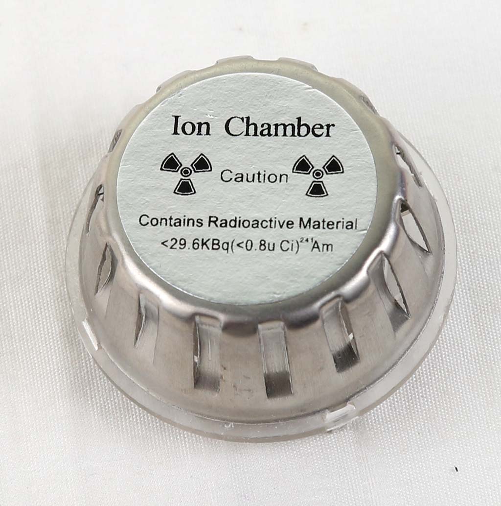
HIS-07 Ionization Chamber of Ionization Smoke Detector


The single-source dual-chamber DSCB type ionization chamber designed according to the best performance of computer analogy is dedicated to smoke detectors. As the main component of the smoke detector, the ionization chamber fully complies with the American UL217 standard, the European EN-54-7 standard and the GB4715-93 national standard. The product quality is consistent, and the assembly of the detector does not need to measure the ionization chamber one by one, which is convenient for automated production

Working Principle

When the current of ionized electrons flowing through the inner and outer ionization chambers is unbalanced, the collector is charged until the ionization current reaches equilibrium. When there is no smoke or burning material, the collector keeps the equilibrium potential except for the statistical fluctuation of the ionization current. When smoke enters the ionization chamber, it affects the ionization current. The outer ionization chamber, which is easy to enter the smoke, is more affected than the inner ionization chamber. The ionization current drops, and the collector is recharged until the new equilibrium potential. This potential change can be used to trigger the alarm circuit

Feature

(1) Single-source double-chamber structure; small size, easy to install in a small alarm;

(2) Under the conditions of relative temperature and humidity of 40°C and 95%, the change value of the collected pole equilibrium potential is within the range of basic parameters;

( 3) The structure of the ionization chamber meets the requirements of UL217 Section 9.5 for anti-insect nets;

(4) Stainless steel and polyester materials and metal palladium on the surface of the ionization source have high corrosion resistance;

(5) The collector electrode has a good balance of potential uniformity and dispersion. Low degree, can be used for analog smoke detectors;

(6) All solder joints are pre-coated with solder to facilitate soldering and installation

Technical Specifications

Conditions:

  • Voltage between the cover electrode and the source base electrode (working power supply voltage): 9 V
  • Ambient temperature: 20±3°C
  • Atmospheric pressure: close to standard atmospheric pressure, clean air
Project Numerical Value
Collector Balance Potential .5±0.3 V
Collecting electrode potential varies with smoke concentration  
Dimming rate is 1%/ft 0.6 V
The dimming rate is 4%/ft 2.2V
Insulator leakage current (Max) 0.5 pA
Capacitance (from collector to outer cover + to source base) 6 pF


,


Ionization source characteristics and radiation safety performance

  • Install a high-performance low-activity Am-241 ionization source in the ionization chamber
  • Ionization source activity 0.5μCi(18kBq)±10% 0.8μCi(30kBq)±10%
  • Ionization source alpha spectrum
    • Peak: 4eV±10%
    • FHWM (full width at half maximum): 0.7 MeV
  • Safety polarization standard (GB4075 ≈ ISO2919) C64444
  • The radiation dose rate at 25cm of the ionization chamber is 0.03mGy/year (lower than 1mGy value of human population dose standard)

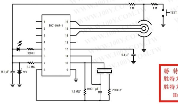
Recommended circuit diagram

If the smoke detector uses MC14467 components, please refer to the following circuit schematic diagram

Sensitivity characteristics


(According to UL217 standard wind speed 0.1M/sec)

Smoke concentration (%/ft)
The Output Voltage (V) Error (ΔV)
0 5.6±0.4 0
1 5.3±0.5 0.3±0.12
2 5.0±0.5 0.6±0.13
3 4.7±0.5 0.9±0.24
4 4.4±0.5 1.2±0.25
5 4.2±0.5 1.4±0.2

Power supply voltage characteristics (25°C.60%RH)

Voltage The output voltage (V)
6 3.3±0.3
9 5.6±0.4
12 8.0±0.7
15 10.0±0.85
18 13.0±1.0

Temperature characteristics: (humidity: 60%)


Humidity characteristics (temperature: 25°C)


Shape and Structure

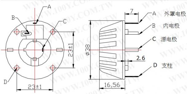
  • A: Cover electrode: connect to positive electrode or power supply positive
  • B: Inner electrode: output signal
  • C: Source electrode: ground wire or power negative
  • D: Pillar

Precaution:

1. To detect the output voltage, a meter or IC integrated circuit (MC14467/14468) with impedance above 1014NM is required. Ordinary instruments will cause inaccurate test results.
2. When assembling the smoke alarm, do not mistake solder and other sundries into the ion chamber of the device, otherwise it must be cleaned.
3. The output leads of the device should be connected in the air (Teflon support leads are generally used), because ordinary circuit boards will cause small leakage currents, which will make the test results inaccurate.
4. The device leads and the input leads of FETs and ICs need to be sealed with epoxy resin to minimize the leakage current caused by humidity.

5. Since the output current of the device is very small, the device needs a mask. Since the output current of the device is very small, the device needs a mask.

Ref


PAM8403 , 3 Watt Class D Amplifier

PAM8403 Amplifier Kelas D


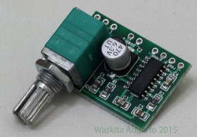
pam8403-IMG_5748
PAM8403 Amplifier Kelas D

Description

The PAM8403 is a 3W, class-D audio amplifier. It offers low THD+N,
allowing it to achieve high-quality sound reproduction. The new
filterless architecture allows the device to drive the speaker directly,
requiring no low-pass output filters, thus saving system cost and PCB
area.
With the same numbers of external components, the efficiency of the
PAM8403 is much better than that of Class-AB cousins. It can extend
the battery life, which makes it well-suited for portable applications.
The PAM8403 is available in SOP-16 package.

Features

  • 3W Output at 10% THD with a 4Ω Load and 5V Power Supply
  • Filterless, Low Quiescent Current and Low EMI
  • Low THD+N
  • Superior Low Noise
  • Efficiency up to 90%
  • Short Circuit Protection
  • Thermal Shutdown
  • Few External Components to Save the Space and Cost
  • Pb-Free Package
    •  

Application

What is PAM8403 for?

  • LCD Monitors / TV Projectors
  • Notebook Computers
  • Portable Speakers
  • Portable DVD Players, Game Machines
  • Cellular Phones/Speaker Phones
    •  

Typical Application Circuit

Rangkaian PAM8403
Typical circuit for PAM8403

Pin List

Pin number Pin name Pin Function
1 +OUT_L Left Channel Positive Output
2 PGND Power GND
3 -OUT_L Left Channel Negative Output
4 PVDD Power VDD
5 MUTE Mute Control Input (active low)
6 VDD Analog VDD
7 INL Left Channel Input
8 VREF Internal analog reference, connect a bypass capacitor from VREF to GND.
9 NC No Connact
10 INR Right Channel Input
11 GND Analog GND
12 SHND Shutdown Control Input (active low)
13 PVDD Power VDD
14 -OUT_R Right Channel Negative Output
15 PGND Power GND
16 +OUT_R Right Channel Positive Output

 Functional Block Diagram

PAM8403 Functional Block Diagram

Absolute Maximum Rating

These are stress ratings only and functional operation is not implied. Exposure to absolute maximum ratings for prolonged time periods may
affect device reliability. All voltages are with respect to ground.

Parameter Rating Unit
Supply Voltage 6.0 V
Input Voltage V -0.3 to VDD +0.3V V
Operation Temperature Range -40 to +85 °C
Maximum Junction Temperature 150 °C
Operation Junction Temperature -40 to +125 °C
Storage Temperature -65 to +150 °C
Soldering Temperature 300, 5 sec °C

References

Datasheet TRIAC BT151

Datasheet TRIAC BT151

General Description

Glass passivated thyristors ina plastic envelope, intended for use in applications requiring high bidirectional blocking voltage capability and high thermal cycling performance. Typical applications include motor control, industrial and domestic lighting, heating and static switching.

Quick Reference Data

 
Symbol Parameter MAX MAX MAX UNIT
    BT151-500R BT151-600R BT151-800R  
VDRM, VRRM Repetitive peak off state voltages 500 650 800 volt
IT

Average on-state current

7.5 7.5 7.5 ampere
IT(RMS) RMS on state current 12 12 12 ampere
ITSM Non repetitive peak on state current 100 100 100 ampere

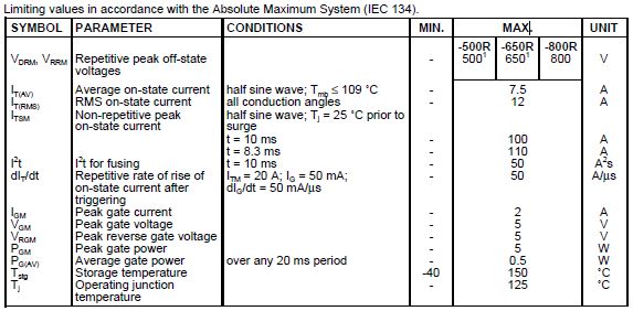
Limiting Values

BT-151 Limiting Values

Referensi


Lightning Rod and Surge Arrester

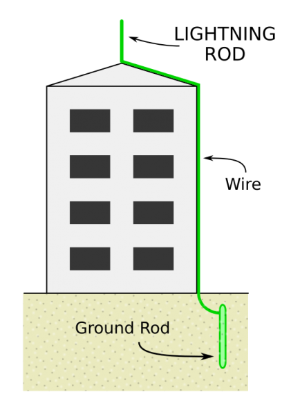
Lightning Rod
Lightning Rod

Lightning Guards for antennas
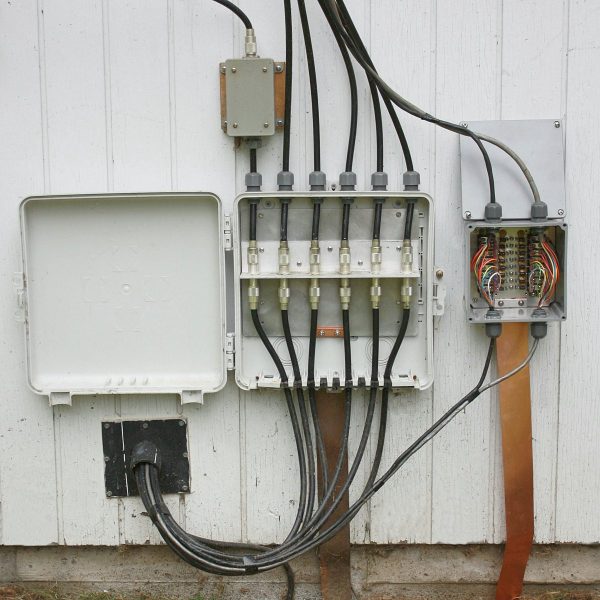
Arrester surge Panels

Both have different functions. It is better to install both.

  • The lightning rod solves the problem of direct strike.
  • Surge arrester overcome indirect struck problem.

Lightning rod function for lightning strikes not about buildings or devices. The current from lightning is disposed to large cable land. If the current passes through the building, then the building can be burned/damaged.

The current of lightning can generate magnetic field, which can get into power cord or other cables nearby. This current induction can be entered into an electronic device. Surge arrester functions throw more current/voltage on the wires to the ground, so the current does not go into the device.