Problems:
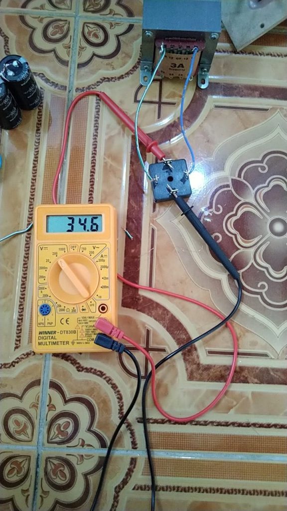
Want to raft amps using a CT 18 VAC transformer But after passing the Spull diode so 34 VDC
The circuit is a full-wave bridge rectifier, with the following schemes (source):
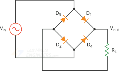
The signal form of the above series is still not flat, because there are no filter capacitors yet.
The input voltage takes from the terminal 18 volts and 18, while the transformer has a tap center (CT), so the AC voltage that goes into the bridge diode is 18 volt RMS (root mean square).
To illustrate this signal, it needs to be converted to peak voltage, with the formula Vpeak = Vrms * 1,414, so Vpeak = 36 x 1,414 = 50,904 Volt
The bridge output voltage form is as follows (green color signal), compared with the input signal (red color):
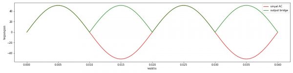
Actually, the bridge output signal will be reduced slightly as there is a drop voltage on the diode, but in that image the drop voltage is ignored first.
If the bridge output voltage is measured by DC voltmeters, then the measured voltage is the average of the green color. The formula is Vaverage = 0637 Vmax = 0.9 Vrms
SOURCE rumurs: https://www.electronics-tutorials.ws/power/single-phase-rectification.html
The diagram as follows:
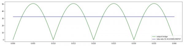
The green signal is the output of the bridge, the synusoidal signal that has already been seared.
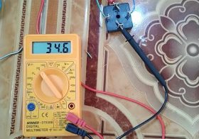
The measured voltage at the DC voltmeter is the average of 32.4 volts
In measured photos is 34.6 volts, likely due to imprecision of the output voltage of the transformer. If you want more definite, it can be measured how much the output voltage of the transformer or bridge inputs with the AC voltmeter (AVOmeter on the AC setting).
Tip: The standard AVOmeter on the DC setting is only designed to measure DC or average voltage, while in the AC setting only for measuring AC rms voltage (root-mean-square). If the form of the signal is not a DC or pure AC, then the displayed number is less precise. On a signal that is not DC or AC is pure, it is more appropriate to use an oscilloscope to measure the signal.