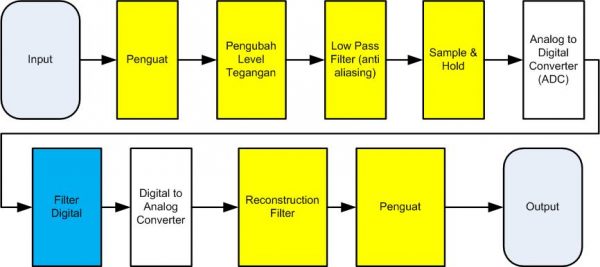
A digital filter system in principle has a diagram block as follows:

In practice, the system needs some additional details in order to be implemented with a microprocessor or digital system (e.g. FPGAS).
Here is a complete system of digital filters to implement with the microprocessor system:

Explanation
- Input: input signal derived from input, e.g. for audio system can be microphone, or MP3 player, or computer.
- This input signal has a certain level of voltage and impedance. Often these signals need to be strengthened first. E.g. microphones usually have a strong signal of tens to hundreds of millivolts with a hundreds of ohm impedance.
- Amplifier: Amplifier has buffering function and also adjusts the amplitude to match the amplitude of used ADC.
- Voltage Level changer: the input voltage in the form of alternating voltage, can have positive and negative voltage. The ADC used can often only accept positive voltages, so the input voltage must be shifted to be positive.
- Low Pass Filter (anti aliasing): According to signal theory, the sampling frequency has at least 2x the frequency of the signal working frequency measured. The input signal more than 1/2 sampling frequency must be filtered so as not to happen aliasing.
- ADC (Analog to Digital Converter): Converts the Analog voltage into a Digital number, with a certain bit resolution, and a specific sampling rate.
- Digital Filter: Perform the desired signal processing process, can be LPF (Low pass filter), HPF (High pass filter), BPF (band pass Filter), BSF (band stop Filter) or Equalizer.
- Digital to Analog Converter: Converts the digital signal into an Analog signal. It generally uses the principle of ZoH (Zero order Hold).
- Reconstruction Filter: The signal from Zero order Hold has a ladder-like staircase, so it has a high frequency component. Therefore, there needs to be a reconstruction filter that removes the high-frequency component. In addition, ZoH also changes the frequency response, giving attenuation at high frequencies. Ideally reconstruction filter also compensates for it.
- Amplifier: To adjust the voltage and impedance level from the DAC to the next stage
- Power supply: Implicit all electronics systems need power supply. Digital processing systems have analog and digital parts, so they need to have their own voltage and power supply level.
The above system is already working well, but it has some disadvantages:
First issue: Conversion of analog to digital
- Anti aliasing filter is difficult to create ‘ sharp ‘, so the sampling frequency must be much higher than the signal working frequency. If the sampling frequency is too close, the working frequency response is affected by an anti aliasing filter, or also some high frequency signal may penetrate the anti-aliasing filter.
- Due to the high sampling frequency, the digital filter section must work at a higher frequency than the signal working frequency.
- It also affects if the signal needs to be stored: storage will grow
- It also affects if the signal needs to be sent: communication bandwidth needs to grow.
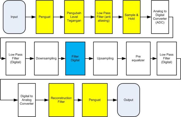
- Solution: Sampling is performed with a high frequency, but the sampling frequency is lowered (downsampling) before the signal is processed/shipped/stored.
- In the downsampling process, the signal needs to be filtered digitally so that it does not occur aliasing. Digital filter process is easier than analog filter, especially due to the accuracy problem of analog component value.
Second issue: Digital conversion to analog
Zero order Hold on the DAC has a frequency response sinc (), so there is attenuation at high frequencies
- Solution 1: The digital signal is changed to a high frequency before going into the DAC, thus the influence of high-frequency attenuation decreases.
- Solution 2: The digital signal is reinforced first at high frequencies with the equalizer, in order to compensate for attenuation in high frequencies.
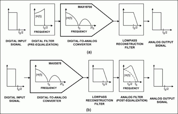
Here is the process of signal equalization to compensate for the effect of ZoH.

In the solution (a) The equalization process is performed digitally before the DAC, referred to as the pre-equalization stage.
In the solution (b) The equalization process is performed analogous after the LPF, referred to as the post-equalization stage.
Here is a diagram block of digital filter system with these solutions:

In this system was selected pre-equalization digitally, with consideration of designing the equalizer digitally easier. The process of creating this equalizer can be done by the ‘ Design of FIR Filters Using the Frequency Sampling method ‘ method.
Reference
- Digital Signal Processing Simulation
- Lizhe Tan, Jean Jiang, Digital Signal Processing (Third Edition) Fundamentals and Applications, Elsevier, 2019
- Steven W. Smith,, The Scientist and engineer’s Guide to Digital Signal Processing http://www.dspguide.com/
- Equalizing Techniques Flatten DAC Frequency Response https://www.maximintegrated.com/en/design/technical-documents/app-notes/3/3853.html
- Flatten DAC frequency response, Electronic Design Network https://www.edn.com/flatten-dac-frequency-response/
- Designing an anti-aliasing filter for ADCs in the frequency domain http://www.ti.com/lit/an/slyt626/slyt626.pdf
