Artikel-Artikel ESP32 selanjutnya akan ditampilkan di situs https://esp32.iptek.web.id/
Kategori: Uncategorized
Noise pada Op-Amp Bipolar vs FET dan Tabung Vakum
Pernyataan menarik kenapa tabung vakum suaranya lebih ‘bagus’ dibandingkan transistor bipolar. Op-amp modern banyak yang menggunakan JFET dan MOSFET. Konon suaranya lebih bagus.
“Many audio experts believe that the sound quality of a high performance FET op amp is superior to that of bipolar op amps. A possible reason for this is that bipolar designs generate greater od-order harmonics than FETs. To the human ear, odd-order harmonics have long been identified as sounding more unpleasant than even-order harmonics. FETs, like vacuum tubes, have a square-law I-V transfer function which is more linear than the exponential transfer function of a bipolar transistor. As a direct result of this square-law characteristic, FETs produce predominantly even-or- der harmonics.”
Membaca Nilai GPIO pada ESP32 tanpa fungsi digitalRead()
Berikut ini akan ditujukkan cara membaca Nilai GPIO pada ESP32 tanpa fungsi digitalRead(). Membaca GPIO dengan digitalRead() praktis secara programming, namun relatif lambat.
#include "soc/gpio_struct.h" // Include the GPIO register definitions
//##include "soc/io_mux_reg.h" // Include the IO_MUX register definitions
// Define the GPIO pin number
const int gpioPin = 18;
void setup() {
Serial.begin(115200);
pinMode(gpioPin, INPUT_PULLUP); // Enable pull-up
}
void loop() {
// Read the GPIO input register
bool gpio18_state = (GPIO.in >> 18) & 0x01;
Serial.print("GPIO 18 state: ");
Serial.println(gpio18_state);
delay(100);
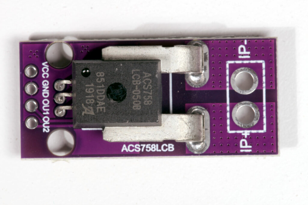
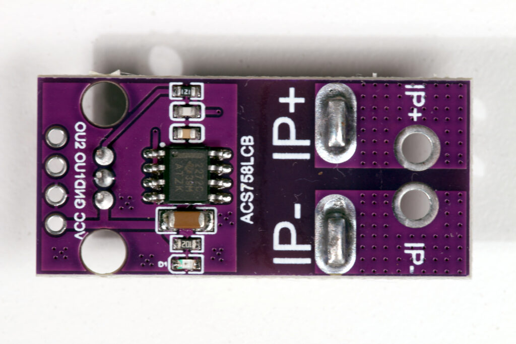
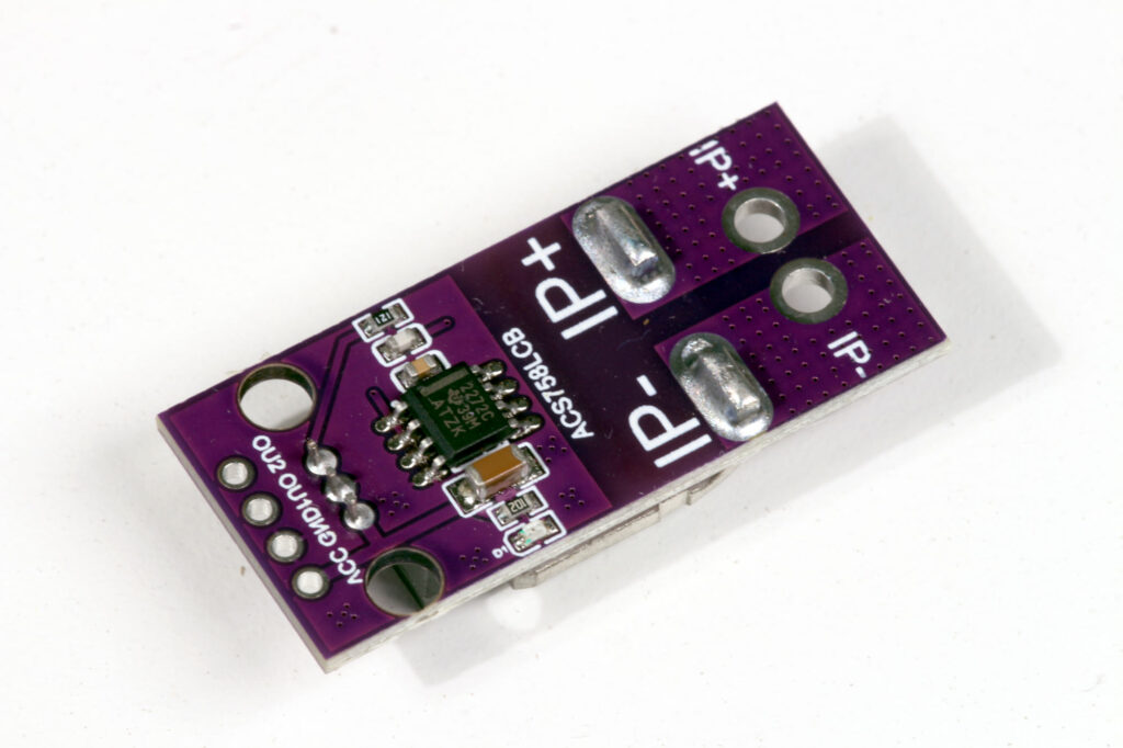
}Modul Sensor Arus ACS758
Berikut ini beberapa foto modul pengukur arus ACS758 yang menggunakan Hall-Effect sensor di dalamnya.
Beberapa literatur untuk mempelajari ACS758:
- Article on ACS758 breakout board https://www.best-microcontroller-projects.com/acs758.html
- Datasheet ACS758 https://www.best-microcontroller-projects.com/support-files/acs758.pdf
- Perbandingan berbagai cara untuk mengukur arus https://datacapturecontrol.com/articles/io-components/sensors/current
Perhitungan Daya Speaker Aktif Dengan Baterai
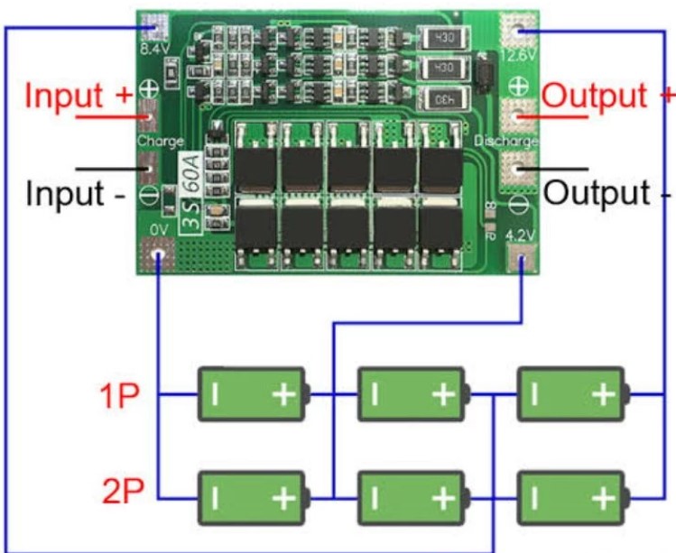
Suatu speaker aktif 12V dapat diberi daya dari adaptor 12V maupun menggunakan baterai. Jika menggunakan baterai yang bisa diisi ulang seperti Li-Ion, sebaiknya menggunakan komponen BMS (Battery Management System) supaya penggunaan baterai lebih baik.
Berikut ini contoh penggunaan BMS dengan 6 baterai.
BMS memiliki beberapa fungsi berikut ini:
- Pengaman untuk charging, supaya tidak terjadi overcharge, ataupun kesalahan arus/ tegangan untuk pengisian
- Memastikan tegangan pada baterai yang diseri seimbang. Baterai yang telah diisi ulang berkali-kali dapat saja mengalami perubahan tegangan karena kecepatan pengisian pada setiap baterai berbeda.
- Pengaman kalau baterai sudah habis. Baterai isi ulang biasanya bisa rusak kalau dipaksa dipakai walaupun sudah habis isinya.
Berikut ini perhitungan durasi pemakaian baterai tersebut. Asumsi:
- speaker aktif mendapatkan energi dari baterai dengan BMS 40A
- jumlah baterai yang dipakai 6 buah
- susunan baterai seri paralel, paralel 2, diseri 3.
- tegangan baterai 4,2 volt (tegangan 18650 bisa dari 3,7 volt sampai 4,2 volt)
- kapasitas baterai 2600 mAh
Pertanyaan:
(1) berapa lama mampu dipakai untuk menyalakan speaker aktif 30 watt
(2) jika speaker aktif tersebut menggunakan adaptor, perlu berapa ampere
Jawaban (1):
Jika dianggap efisiensi amplifier adalah 100%, maka perhitungan sebagai berikut:
energi setiap baterai = tegangan baterai (volt) x kapasitas muatan baterai (Ah)
jumlah energi di semua baterai = 6 x tegangan baterai x kapasitas baterai
total energi tersimpan di baterai = 6 x 4,2 volt x 2600 mAh = 10,92 VAh = 65,52 Wh
waktu = energi / daya = 65,52 Wh / 30 watt = 2,184 jam = 2 jam 11 menit
Dalam prakteknya efisiensi amplifier bisa antara 50% ~ 90%, jadi durasi penggunaannya akan kurang dari 2 jam 11 menit.
Jika misalkan efisiensi = 50%, maka durasi akan menjadi: 2,184 jam x 50% = 1,092 jam
Jawaban (2)
Daya 30 watt
tegangan 12 volt
asumsi efisiensi 100% (semua daya dari adaptor menjadi energi suara)
daya = tegangan x arus
P = V x I
daya dan tegangan diketahui, tinggal menghitung arus.
I = P / V = 30 watt / 12 ampere = 2,5 ampere
Jadi diperlukan adaptor 2,5 ampere
Dalam prakteknya akan ada inefisiensi, jadi lebih baik pakai adaptor yang lebih dari 2,5 ampere
Op Amp Populer
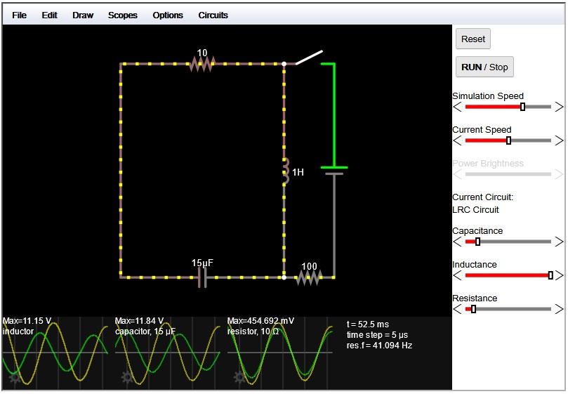
Simulasi Rangkaian Elektrik Online
Falstadt, simulator rangkaian elektrik Online. Antar mukanya menggunakan graphical, jadi sangat mudah. Visualisasi arus di setiap kabel juga bagus.
Falstadt
Simulator ESP32
- Wokwi, mengklaim sebagai “World’s most advanced ESP32 simulator”. Dapat melakukan simulasi Arduino (Uno, Mega, Nano), ESP32, STM32 dan Pi Pico. Ada versi onlinenya di website Wokwi, dan ada juga versi offline yang dapat diinstall di VS Code / JetBrains (berbayar). Ada juga versi Wokwi Pro (berbayar) yang dapat diintegrasikan ke CI (Continous Integration).
Komponen Grounding
Berikut ini beberapa komponen yang diperlukan untuk memasang grounding perangkat:
- Grounding Rod : jumlah sesuai kedalaman yang diperlukan
- Ground Clamp: dipakai untuk menyambung grounding rod ke kabel grounding
- Ground Bus Bar : untuk membuat percabangan kabel grounding ke perangkat-perangkat yang memerlukan
- Kabel Grounding dari bahan tembaga
Driver Motor MX1616
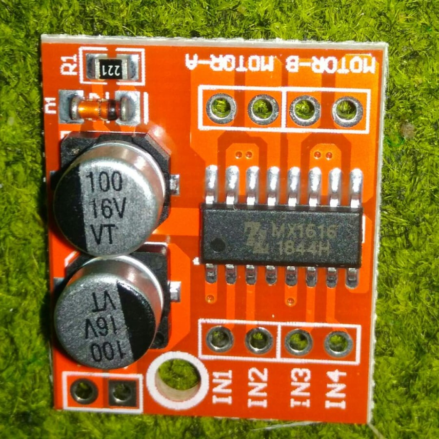
Skema Modul MX1616
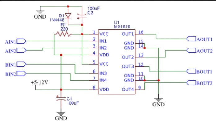
Literatur
- Datasheet MX1616H
- Tutorial for Arduino Mini DC Motor Driver Dual H-Bridge PWM Control
- MX1616 H-Bridge DC Motor Driver
Nilai Resistor dan Kapasitor untuk Rangkaian Operational Amplifier
Panduan pemilihan nilai resissor dan kapasitor untuk rangkaian dengan op-amp:
- Nilai resistor antara 1k ~ 100kΩ
- Nilai kapasitor antara 1 nF ~ beberapa μF
Kutipan:
Resistor values should stay within the range of 1–100 kΩ. The lower limit avoids excessive current draw from the op amp output, which is particularly important for single-supply op amps in power-sensitive applications. Those amplifiers have typical output currents of between 1 mA and 5 mA. At a supply voltage of 5 V, this current translates to a minimum of 1 kΩ.
The upper limit of 100 kΩ is to avoid excessive resistor noise.
Capacitor values can range from 1 nF to several μF. The lower limit avoids coming too close to parasitic capacitances. If the common-mode input capacitance of the op amp, used in a Sallen–Key filter section, is close to 0.25% of C1, (C1/400), it must be considered for accurate filter response. The MFB topology, in comparison, does not require input-capacitance compensation.
Sumber:
- https://www.sciencedirect.com/topics/engineering/resistor-value
- https://www.sciencedirect.com/book/9780128116487/op-amps-for-everyone
Error pada ESP32: Guru Meditation Error: Core 1 panic’ed (Interrupt wdt timeout on CPU1).
Salah satu pesan kesalahan yang dapat muncul pada ESP32 adalah “Guru Meditation Error: Core 1 panic’ed (Interrupt wdt timeout on CPU1)”. Salah satu penyebabnya adalah memanggil Serial.print() dari interupsi
Berikut ini pesan kesalahan yang muncul pada ESP32
Guru Meditation Error: Core  1 panic'ed (Interrupt wdt timeout on CPU1).

Core  1 register dump:
 PC      : 0x4008ab86  PS      : 0x00060535  A0      : 0x80089afe  A1      : 0x3ffbf19c
 A2      : 0x3ffbd448  A3      : 0x3ffbd2d8  A4      : 0x00000004  A5      : 0x00060523
 A6      : 0x00060523  A7      : 0x00000001  A8      : 0x3ffbd2d8  A9      : 0x00000018
 A10     : 0x3ffbd2d8  A11     : 0x00000018  A12     : 0x00000004  A13     : 0x00060523
 A14     : 0x007bf318  A15     : 0x003fffff  SAR     : 0x0000000a  EXCCAUSE: 0x00000006
 EXCVADDR: 0x00000000  LBEG    : 0x400863f9  LEND    : 0x40086409  LCOUNT  : 0xfffffffe
 Core  1 was running in ISR context:
 EPC1    : 0x400db223  EPC2    : 0x00000000  EPC3    : 0x00000000  EPC4    : 0x00000000


 Backtrace: 0x4008ab83:0x3ffbf19c |<-CORRUPTED


 Core  0 register dump:
 PC      : 0x4008ad1b  PS      : 0x00060035  A0      : 0x80089727  A1      : 0x3ffbea3c
 A2      : 0x3ffbf318  A3      : 0xb33fffff  A4      : 0x0000abab  A5      : 0x00060023
 A6      : 0x00060021  A7      : 0x0000cdcd  A8      : 0x0000abab  A9      : 0xffffffff
 A10     : 0x3ffc1f58  A11     : 0x00000000  A12     : 0x3ffc1f54  A13     : 0x00000007
 A14     : 0x007bf318  A15     : 0x003fffff  SAR     : 0x0000001d  EXCCAUSE: 0x00000006
 EXCVADDR: 0x00000000  LBEG    : 0x00000000  LEND    : 0x00000000  LCOUNT  : 0x00000000


 Backtrace: 0x4008ad18:0x3ffbea3c |<-CORRUPTED


 ELF file SHA256: e85d33667e5fa1a7

 Rebooting...
Berikut ini contoh program yang menyebabkan kesalahan tersebut.
// https://www.arduino.cc/reference/en/libraries/esp32timerinterrupt/
#define LED_BUILTIN 22

hw_timer_t *My_timer = NULL;

int kerja_counter = 0;
int print_job = 0;
long int timer_delay = 1000000L;  // clock timer= 1 MHz

void IRAM_ATTR onTimer() {
  digitalWrite(LED_BUILTIN, !digitalRead(LED_BUILTIN));
  kerja_counter++;
  Serial.print("Test ");
  Serial.println(kerja_counter); // bad practice
}

// the setup function runs once when you press reset or power the board
void setup() {
  // initialize digital pin LED_BUILTIN as an output.
  Serial.begin(115200);
  Serial.print(__FILE__);
  Serial.print(F("\nStarting TimerInterruptTest on "));
  Serial.println(ARDUINO_BOARD);
  Serial.print(F("CPU Frequency = "));
  Serial.print(F_CPU / 1000000);
  Serial.println(F(" MHz"));
  pinMode(LED_BUILTIN, OUTPUT);
  My_timer = timerBegin(0, 80, true);  // prescaler
  timerAttachInterrupt(My_timer, &onTimer, true);
  timerAlarmWrite(My_timer, timer_delay, true);
  timerAlarmEnable(My_timer);  //Just Enable
}

// the loop function runs over and over again forever
void loop() {
}
Solusi: Serial.print() dipanggil dari fungsi loop(), sedangkan interupsi hanya mempersiapkan datanya saja, atau menaruh data ke dalam suatu FIFO buffer.
Berikut ini contoh hasil modifikasi program di atas.
// https://www.arduino.cc/reference/en/libraries/esp32timerinterrupt/
#define LED_BUILTIN 22

hw_timer_t *My_timer = NULL;

int kerja_counter = 0;
int print_job = 0;
long int timer_delay = 1000000L;  // clock timer= 1 MHz

void IRAM_ATTR onTimer() {
  digitalWrite(LED_BUILTIN, !digitalRead(LED_BUILTIN));
  kerja_counter++;
  print_job=1;
}

// the setup function runs once when you press reset or power the board
void setup() {
  // initialize digital pin LED_BUILTIN as an output.
  Serial.begin(115200);
  Serial.print(__FILE__);
  Serial.print(F("\nStarting TimerInterruptTest on "));
  Serial.println(ARDUINO_BOARD);
  Serial.print(F("CPU Frequency = "));
  Serial.print(F_CPU / 1000000);
  Serial.println(F(" MHz"));

  pinMode(LED_BUILTIN, OUTPUT);

  My_timer = timerBegin(0, 80, true);  // prescaler
  timerAttachInterrupt(My_timer, &onTimer, true);
  timerAlarmWrite(My_timer, timer_delay, true);
  timerAlarmEnable(My_timer);  //Just Enable
  sei();
}

// the loop function runs over and over again forever
void loop() {
  if (print_job == 1) {
    print_job = 0;
    Serial.print("Test ");
    Serial.println(kerja_counter);
  }
}
Simulasi Kendali Digital
Simulasi Kendali Digital dengan Matlab Simulink
Problem: “Design the gain for the antenna azimuth position control system shown in
Figure 13.30(b) to yield a closed-loop damping ratio of 0.5. Assume a sampling interval
of T 0:1 second.”
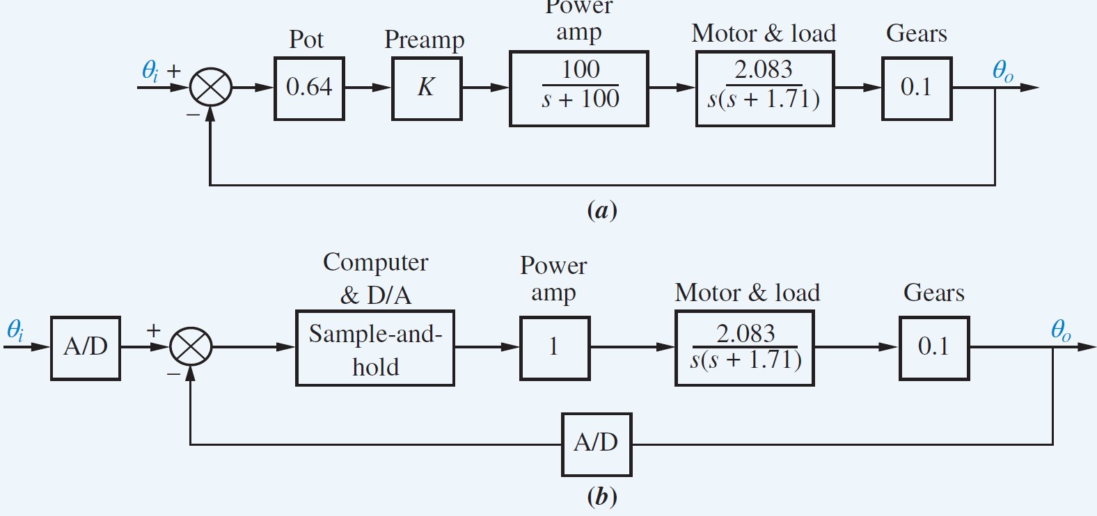 Blok diagram sistem dengan simulink sebagai berikut:
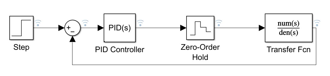 Fungsi transfer sistem dimasukkan ke blok “Transfer Fcn”
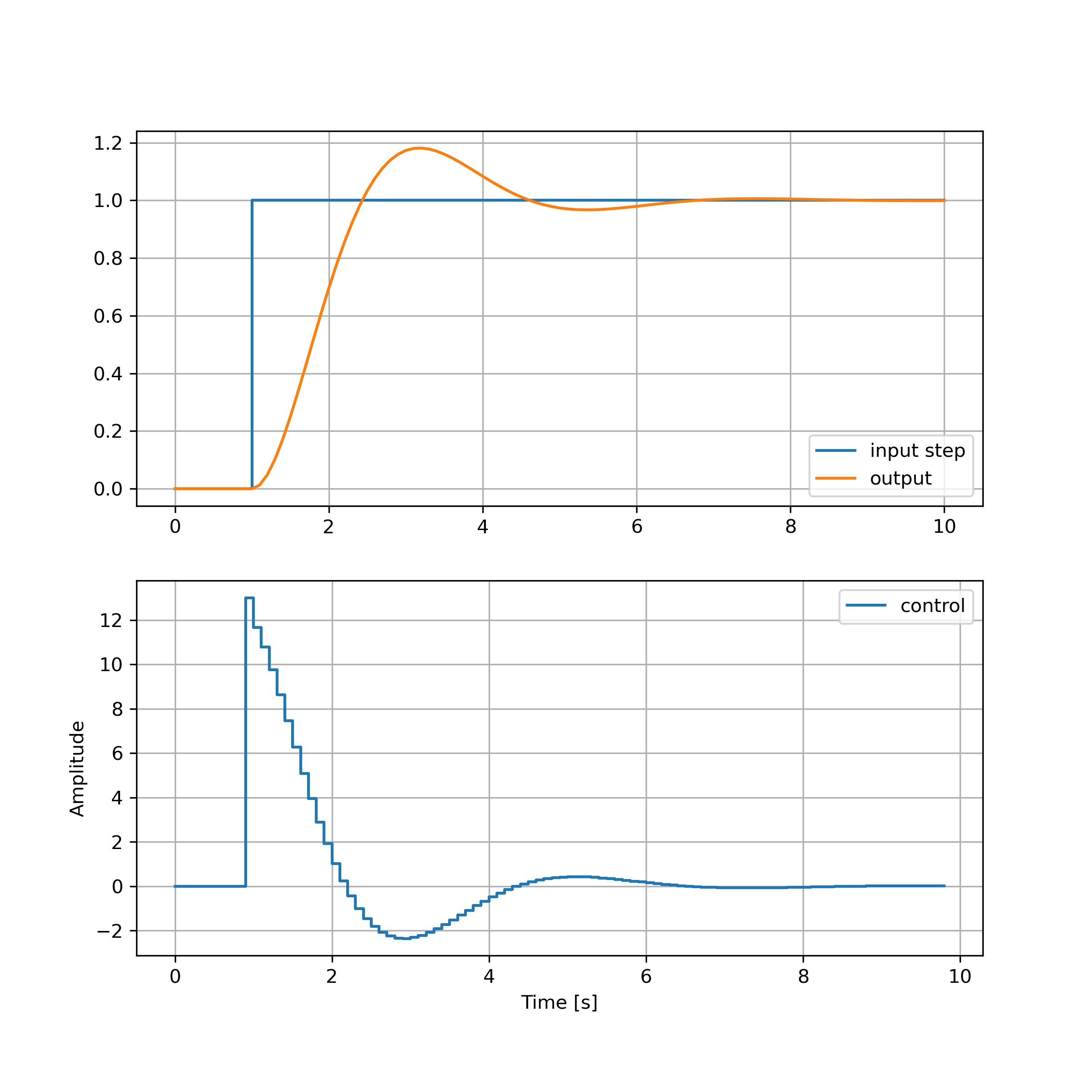
Respon sistem terhadap input step adalah sebagai berikut
Transformasi Bilinear
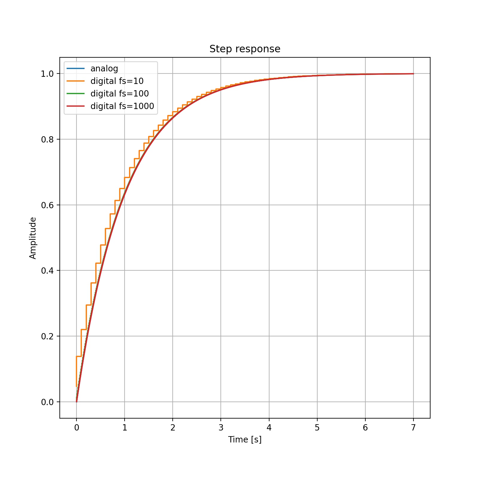
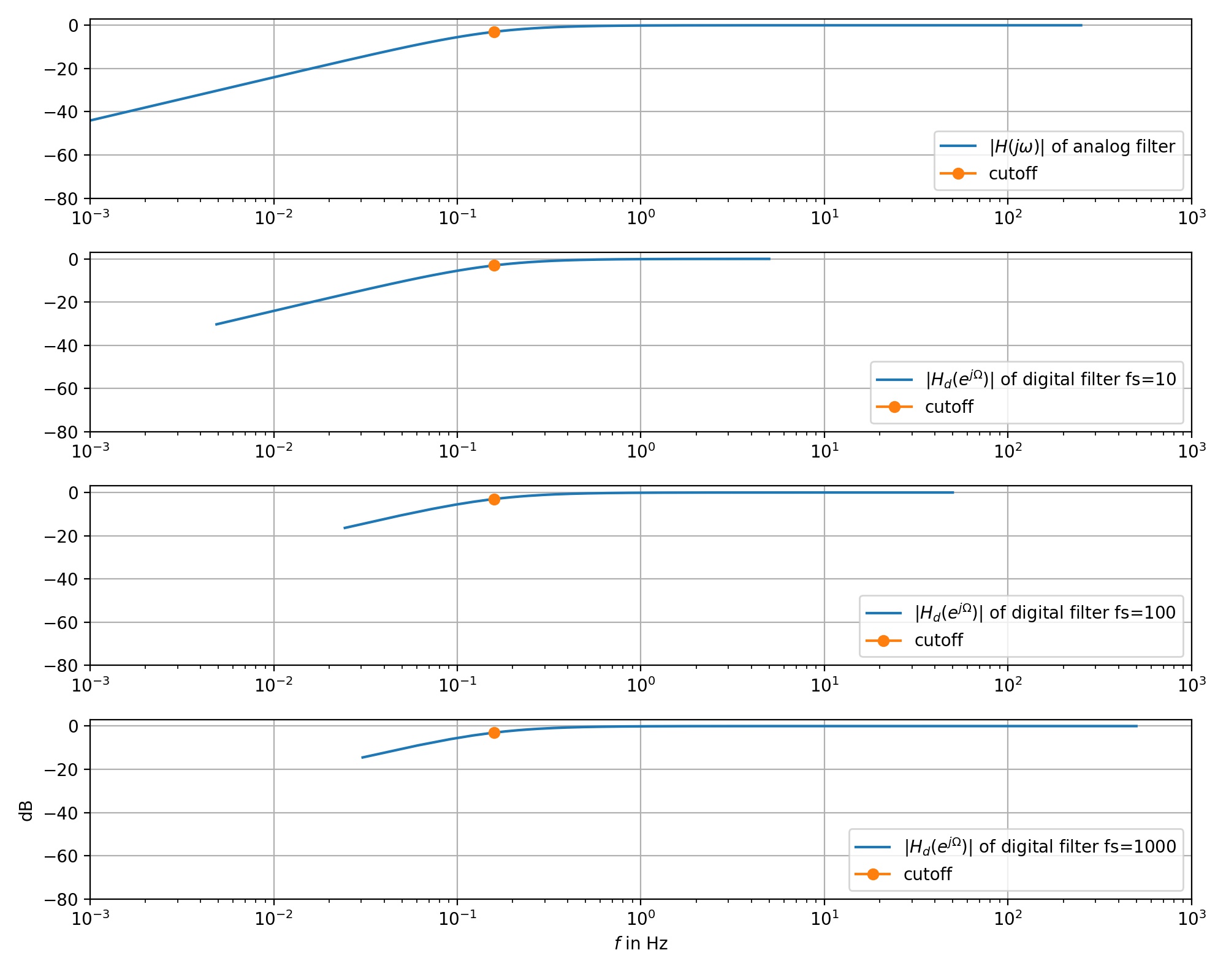
Respon Frekuensi LPF orde 1
Percobaan melihat pengaruh frekuensi sampling terhadap fungsi transfer sistem orde 1 low pass
Fungsi transfer sistem = 1/(s+1)
Time constant = 1, sehingga frekuensi cut off adalah 0.159 Hz
Gambar ilustrasi fungsi transfer untuk filter analog dan filter digital.
Filter digital dicoba dengan beberapa frekuensi sampling: 10 Hz, 100 Hz, 1000 Hz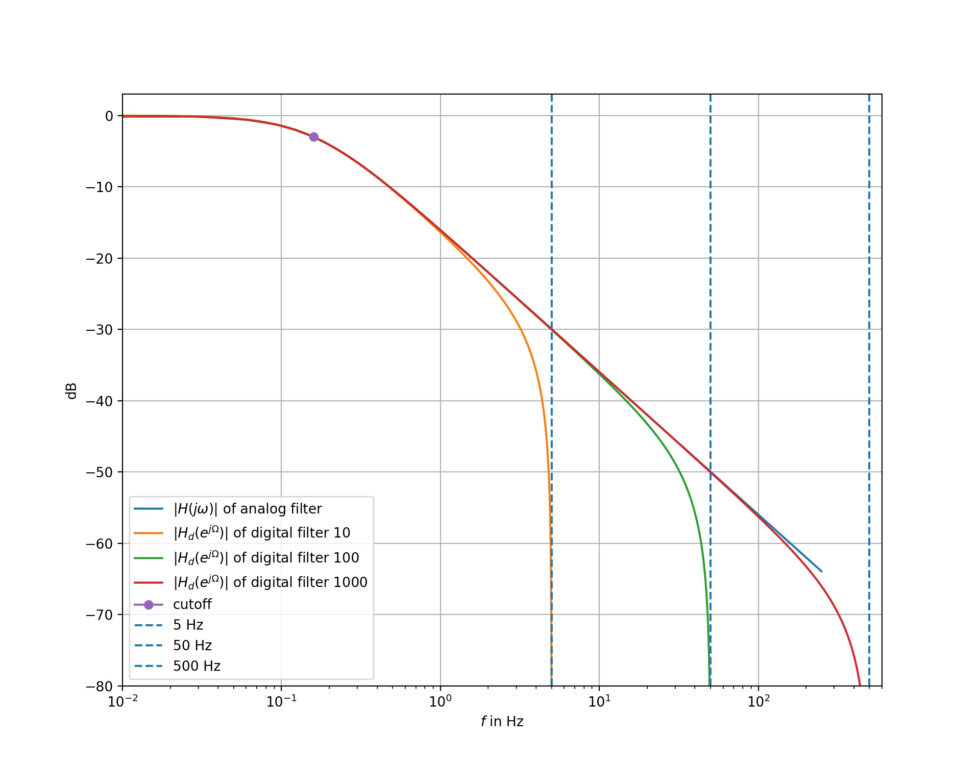
import numpy as np
import matplotlib.pyplot as plt
from scipy import signal
%matplotlib inline

B = [0, 1]
A = [1, 1]

fs10= 10
fs100= 100
fs1000= 1000

fs10_z   = signal.bilinear(B,A,fs10)
fs100_z  = signal.bilinear(B,A,fs100)
fs1000_z = signal.bilinear(B,A,fs1000)

fs10_a  =fs10_z[1]
fs10_b  =fs10_z[0]

fs100_a =fs100_z[1]
fs100_b =fs100_z[0]

fs1000_a=fs1000_z[1]
fs1000_b=fs1000_z[0]
# displaying
plt.figure(figsize=(10, 8))
Om, fs10_Hd   = signal.freqz(fs10_b  , fs10_a, worN=1024)
f10 = Om * fs10 / (2 * np.pi)

Om, fs100_Hd  = signal.freqz(fs100_b , fs100_a, worN=2048)
f100 = Om * fs100 / (2 * np.pi)

Om, fs1000_Hd = signal.freqz(fs1000_b, fs1000_a, worN=16384) # 1000 Hz mesti lebih banyak sampelnya
f1000 = Om * fs1000 / (2 * np.pi)

tmp, H = signal.freqs(B, A, worN=f1000 * Om)
f = Om * f1000 / (2 * np.pi)

plt.semilogx(f, 20 * np.log10(np.abs(H)), label=r"$|H(j \omega)|$ of analog filter")
plt.semilogx(f10, 20 * np.log10(np.abs(fs10_Hd)), label=r"$|H_d(e^{j \Omega})|$ of digital filter 10")
plt.semilogx(f100, 20 * np.log10(np.abs(fs100_Hd)), label=r"$|H_d(e^{j \Omega})|$ of digital filter 100")
plt.semilogx(f1000, 20 * np.log10(np.abs(fs1000_Hd)), label=r"$|H_d(e^{j \Omega})|$ of digital filter 1000")
plt.semilogx(0.159, 20 * np.log10(0.707), marker='o',label="cutoff")
plt.axvline(x = 10/2,   linestyle="--", label = '5 Hz')
plt.axvline(x = 100/2,  linestyle="--", label = '50 Hz')
plt.axvline(x = 1000/2, linestyle="--", label = '500 Hz')
plt.xlabel(r"$f$ in Hz")
plt.ylabel(r"dB")
plt.axis([0.01, 600, -80, 3])
plt.legend()
plt.grid()
plt.savefig("first-order.jpg",dpi=200)
# https://www.geeksforgeeks.org/plot-a-vertical-line-in-matplotlib/
Analisis
- frekuensi warping kelihatan di frekuensi yang makin dekat dengan 1/2 frekuensi sampling
- frekuensi cut off tidak terpengaruh
Respon Step Low Pass Filter orde 1
Respon Frekuensi High Pass Filter orde 1
 Kesimpulan:
- perubahan frekuensi sampling tidak mengubah banyak respon frekuensi filter
Respon Step High Pass Filter orde 1
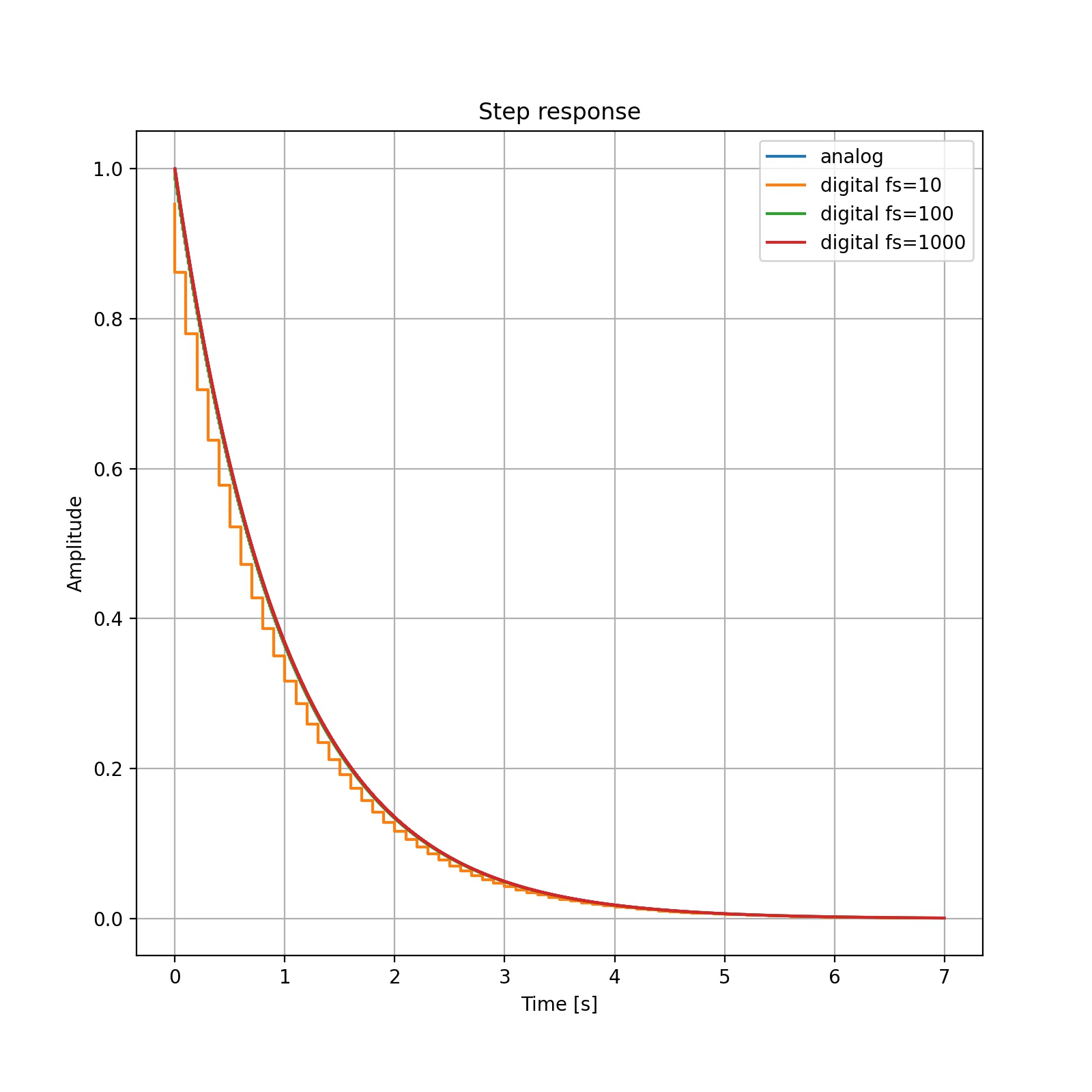 Kesimpulan:
- perubahan frekuensi sampling tidak banyak mengubah bentuk sinyal, kecual pada fs = 10 Hz
Apa itu PWM dan fungsinya?
Apa yang dimaksud dengan PWM, dan apa fungsinya?
PWM (Pulse Width Modulation) adalah modulasi suatu sinyal digital dengan cara mengubah-ubah lebar pulsa tergantung nilai inputnya.
Berikut ini contoh sinyal PWM:
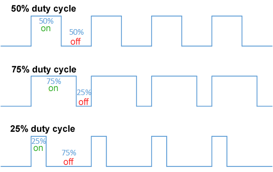
Sinyal PWM memiliki frekuensi tetap. Lebar pulsa diubah-ubah dengan cara mengubah duty-cycle dari sinyal tersebut. Rentang input PWM adalah 0 sampai 100%. Outputnya adalah sinyal dengan frekuensi tetap, namun duty cycle mengikuti input.
Fungsi sinyal PWM di antaranya adalah sebagai berikut:
- sinyal kendali untuk motor servo radio control
- modulasi untuk pengiriman data pada telekomunikasi.
- mengatur daya yang diberikan kepada suatu beban, misal untuk mengendalikan kecepatan putaran suatu motor listrik
- regulasi tegangan. Tegangan output dapat diatur dengan mengubah duty cycle sinyal.
- mengatur kecerahan lampu LED
Berikut ini contoh servo motor yang biasa dipakai di aplikasi radio control:
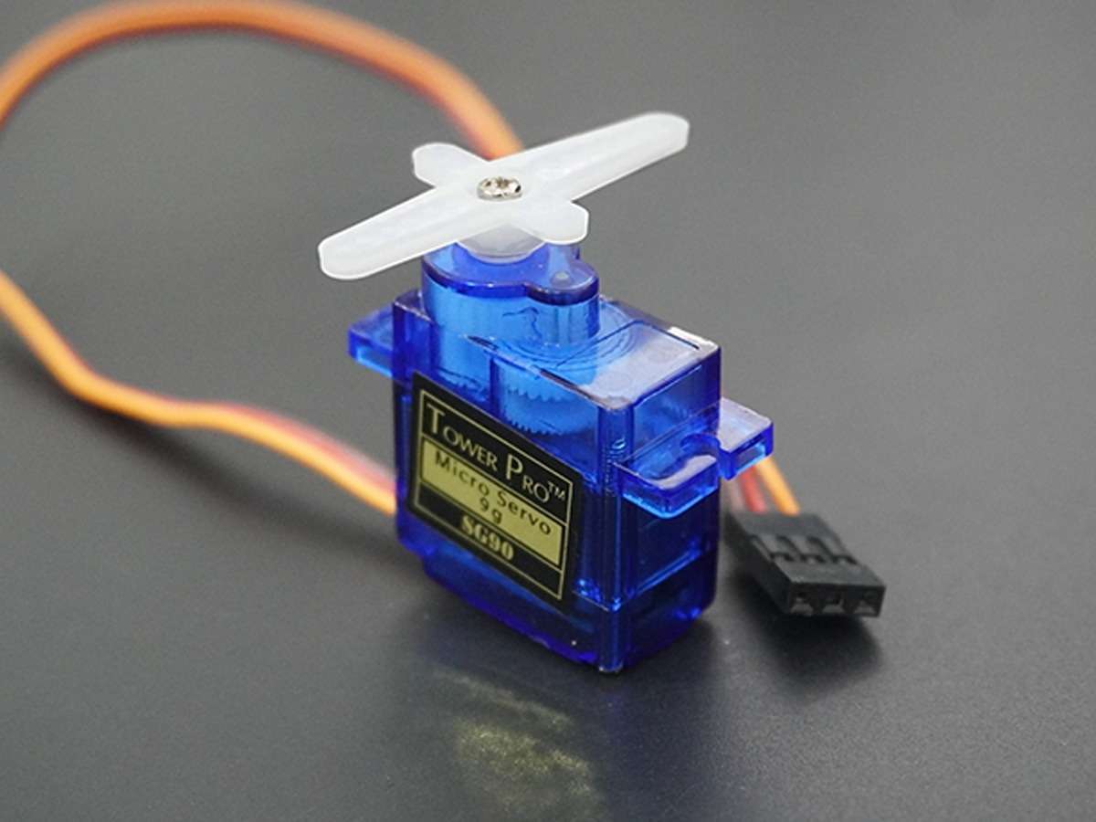
modul motor tersebut memiliki 3 input: VCC, GND dan PWM. Sudut pada poros ditentukan oleh duty cycle pada sinyal PWM.
Referensi
Apa itu Internet of Things
Internet of Things (IoT) adalah perangkat yang memiliki sensor, kemampuan pengolahan/komputasi, perangkat lunak dan teknologi lain untuk menyambungkan dan mengirimkan data ke perangkat lain dan sistem lain melalui internet atau jaringan komunikasi lainnya.
Bidang ilmu Internet of Things melingkupi elektronika, komunikasi dan ilmu komputer.
Tujuan
Tujuan dari Internet of Things adalah memungkinkan semua benda yang dipakai sehari-hari ke internet untuk melakukan pertukaran informasi.
Aplikasi
Contoh aplikasi Internet of Things:
- lampu yang dapat dikendalikan dari jarak jauh melalui smartphone
- Fabrikasi cerdas (smart manufacturing)
- Memonitor aset-aset untuk dapat melakukan perawatan aset sebelum mengalami kerusakan (perawatan pencegahan dan perawatan terprediksi).
- Jaringan distribusi elektrik cerdas
- Kota cerdas
- Logistik yang tersambung ke jaringan komunikasi
- Rantai pasok cerdas
- Pertanian cerdas
- Kesehatan
- Industri retail
- Transportasi
Referensi
- Internet of Things https://en.wikipedia.org/wiki/Internet_of_things
- https://www.oracle.com/id/internet-of-things/what-is-iot/
- https://www.ibm.com/topics/internet-of-things