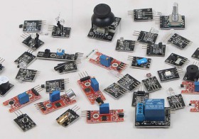
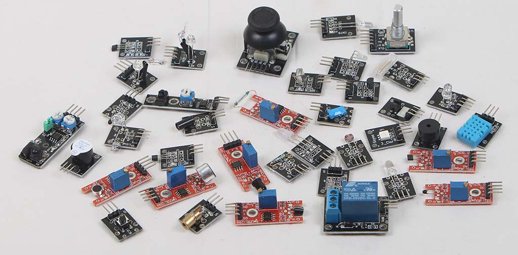
Sensor kit ini dibeli di AliExpress. 1 paket terdiri dari 37 macam sensor. Manual kit ini tidak jelas, jadi perlu usaha ekstra untuk mencari manualnya di Internet.
| No | Nama versi TkkrLab | Nama menurut Linksprite | Foto yang ada | Foto versi TkkrLab | URL TkkrLab | Foto versi linksprite |
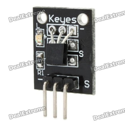
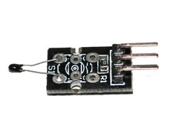
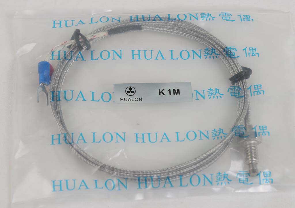
| 1 | KY-001 Temperature sensor module |  |
 |
https://tkkrlab.nl/wiki/Arduino_KY-001_Temperature_sensor_module | ||
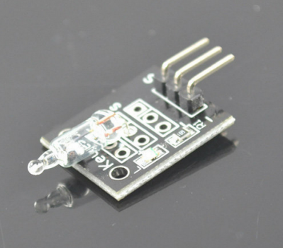
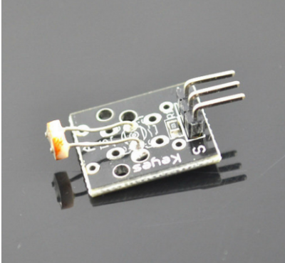
| 2 | KY-002 Vibration switch module | 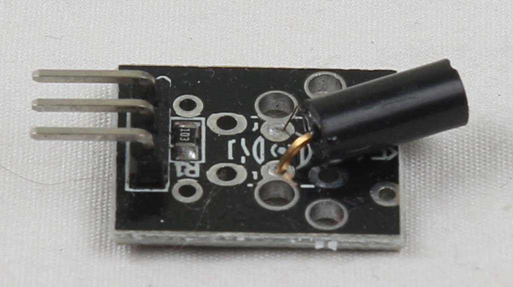 |
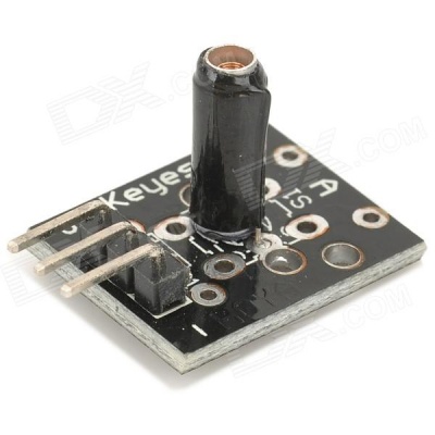 |
https://tkkrlab.nl/wiki/Arduino_KY-002_Vibration_switch_module | ||
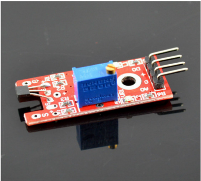
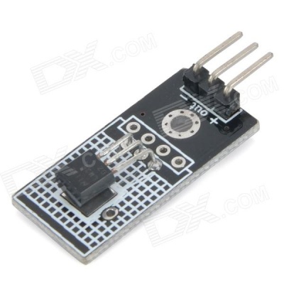
| 3 | KY-003 Hall magnetic sensor module | 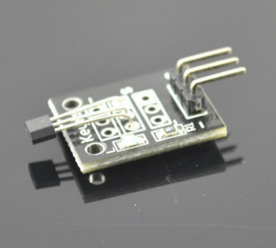 |
https://tkkrlab.nl/wiki/Arduino_KY-003_Hall_magnetic_sensor_module | |||
| 4 | KY-004 Key switch module | 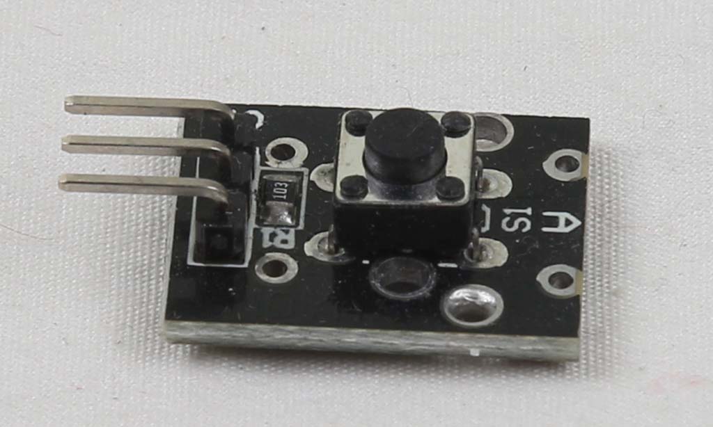 |
 |
https://tkkrlab.nl/wiki/Arduino_KY-004_Key_switch_module | ||
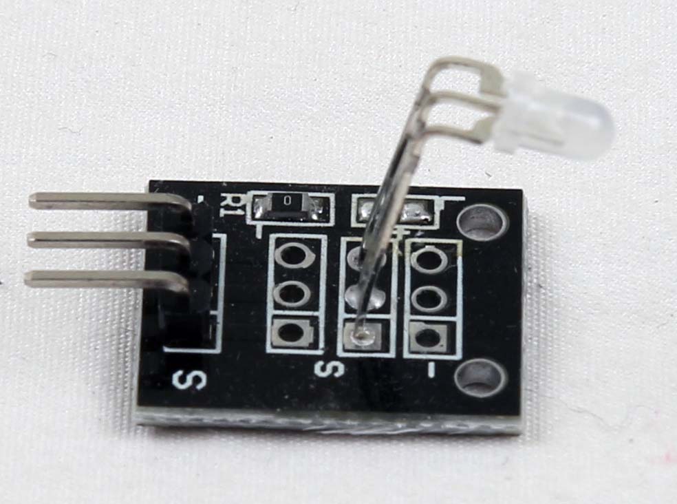
| 5 | KY-005 Infrared emission sensor module | 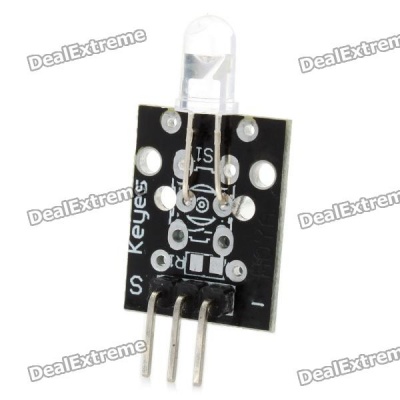 |
https://tkkrlab.nl/wiki/Arduino_KY-005_Infrared_emission_sensor_module | |||
| 6 | KY-006 Small passive buzzer module | 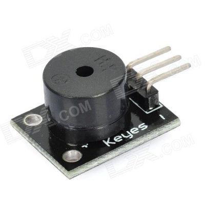 |
https://tkkrlab.nl/wiki/Arduino_KY-006_Small_passive_buzzer_module | |||
| 7 | ||||||
| 8 | KY-008 Laser sensor module | 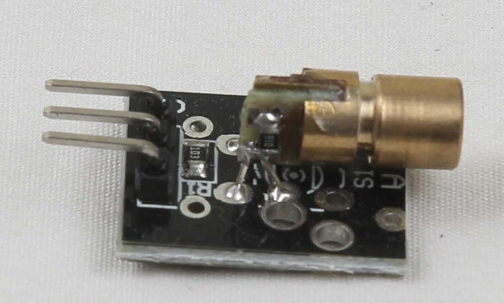 |
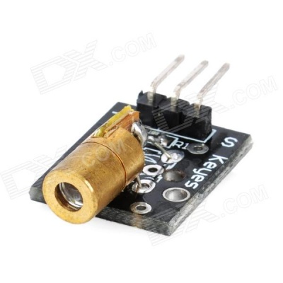 |
https://tkkrlab.nl/wiki/Arduino_KY-008_Laser_sensor_module | ||
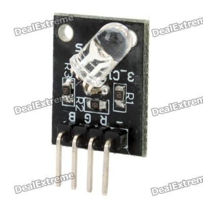
| 9 | KY-009 3-color full-color LED SMD modules | 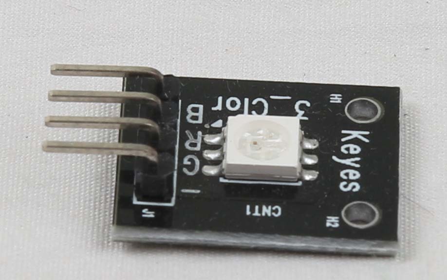 |
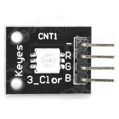 |
https://tkkrlab.nl/wiki/Arduino_KY-009_3-color_full-color_LED_SMD_modules | ||
| 10 | KY-010 Optical broken module | 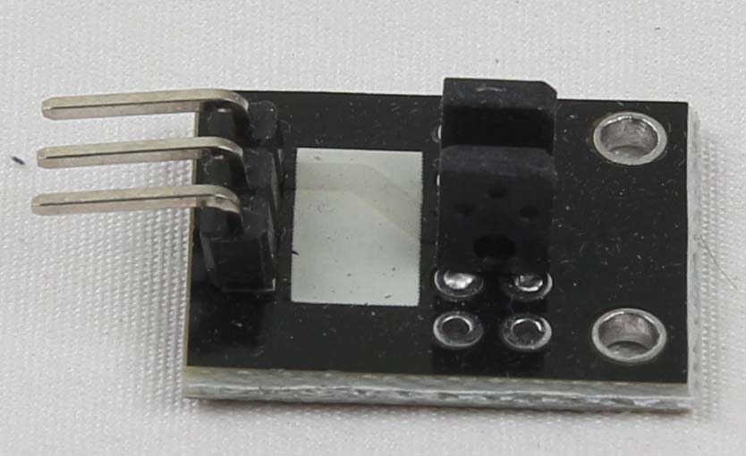 |
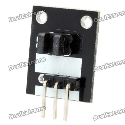 |
https://tkkrlab.nl/wiki/Arduino_KY-010_Optical_broken_module | ||
| 11 | KY-011 2-color LED module |
|
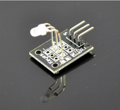 |
https://tkkrlab.nl/wiki/Arduino_KY-011_2-color_LED_module | ||
| 12 | KY-012 Active buzzer module | 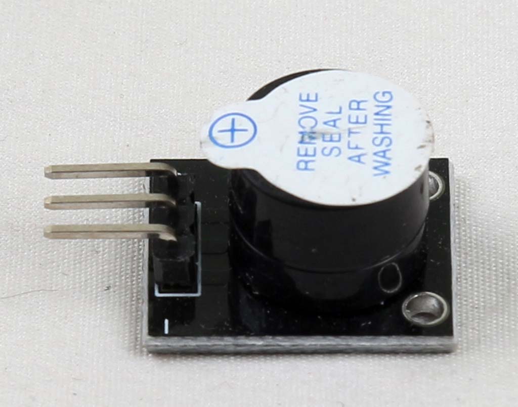 |
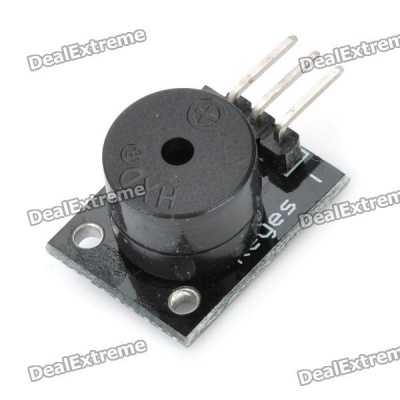 |
https://tkkrlab.nl/wiki/Arduino_KY-012_Active_buzzer_module | ||
| 13 | KY-013 Temperature sensor module | 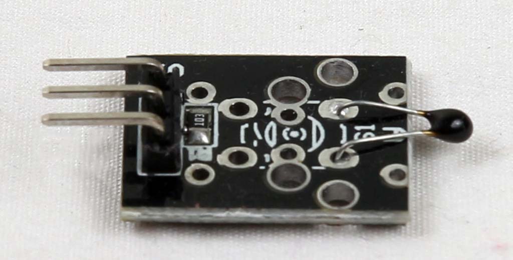 |
 |
https://tkkrlab.nl/wiki/Arduino_KY-013_Temperature_sensor_module | ||
| 14 | ||||||
| 15 | KY-015 Temperature and humidity sensor module | 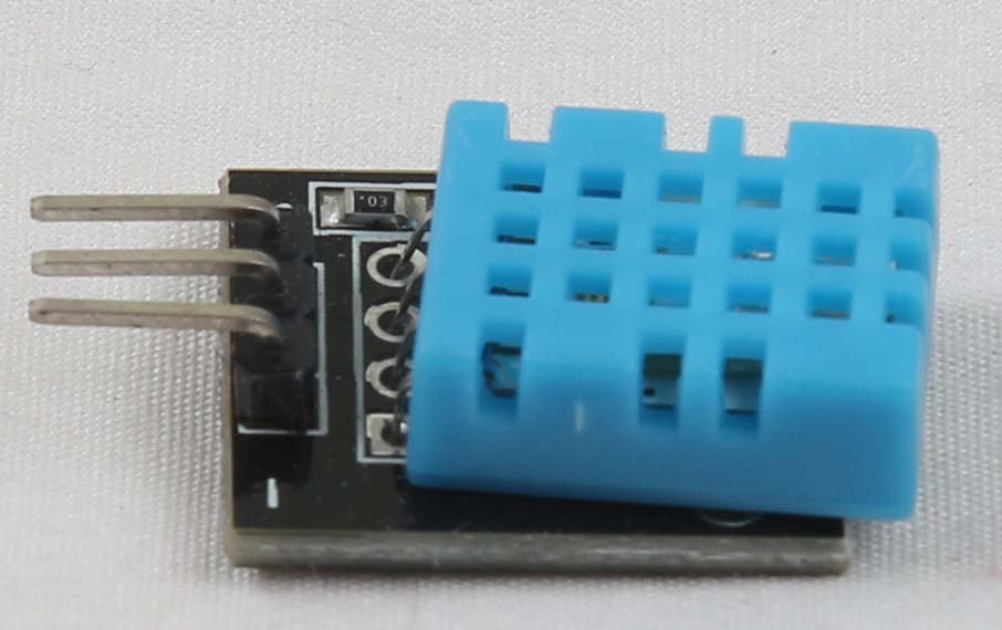 |
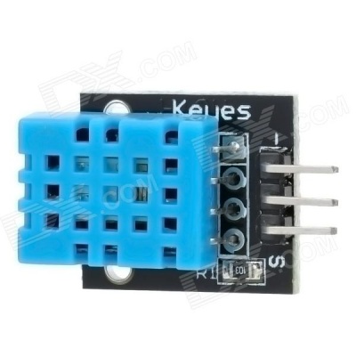 |
https://tkkrlab.nl/wiki/Arduino_KY-015_Temperature_and_humidity_sensor_module | ||
| 16 | KY-016 3-color LED module | KY016:RGB three colors LED module | 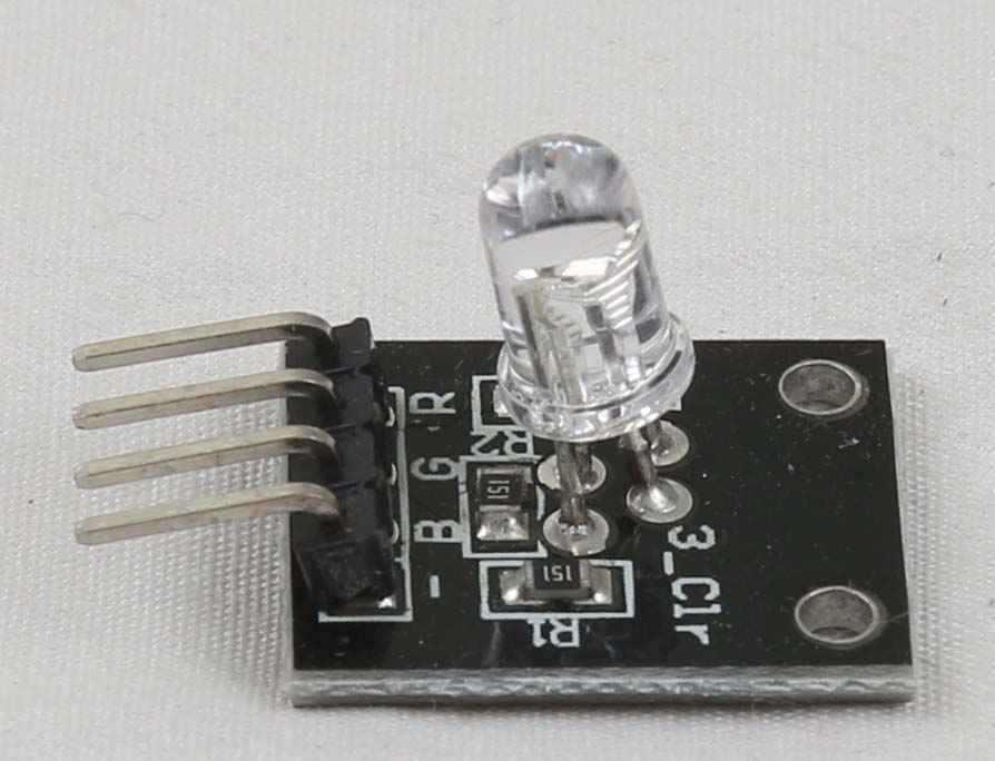 |
 |
https://tkkrlab.nl/wiki/Arduino_KY-016_3-color_LED_module | |
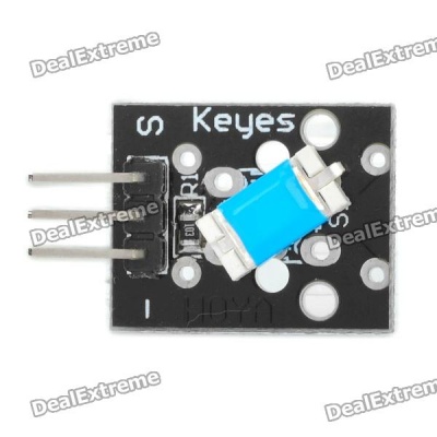
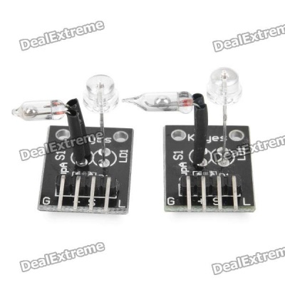
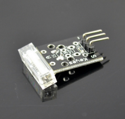
| 17 | KY-017 Mercury open optical module | KY017:Quicksilver Switch Module |  |
 |
https://tkkrlab.nl/wiki/Arduino_KY-017_Mercury_open_optical_module | |
| 18 | KY-018 Photo resistor module |  |
 |
https://tkkrlab.nl/wiki/Arduino_KY-018_Photo_resistor_module | ||
| 19 | KY-019 5V relay module | 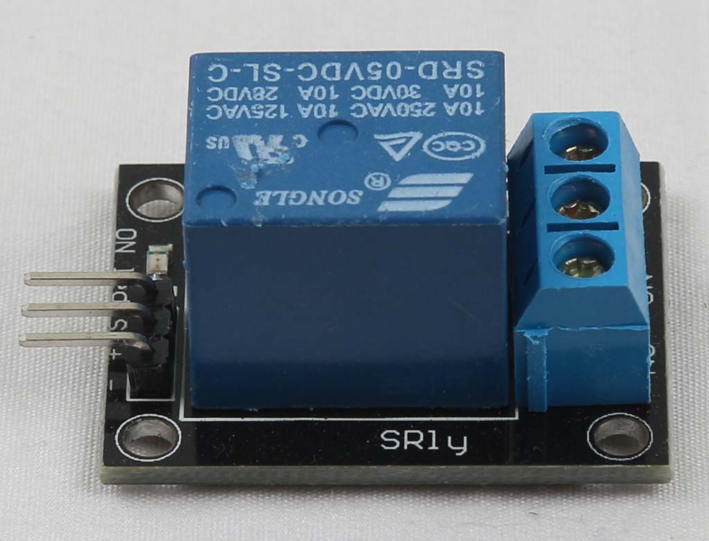 |
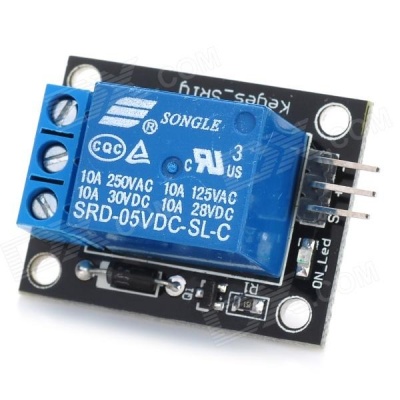 |
https://tkkrlab.nl/wiki/Arduino_KY-019_5V_relay_module | ||
| 20 | KY-020 Tilt switch module |  |
 |
https://tkkrlab.nl/wiki/Arduino_KY-020_Tilt_switch_module | ||
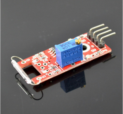
| 21 | KY-021 Mini magnetic reed modules |  |
 |
https://tkkrlab.nl/wiki/Arduino_KY-021_Mini_magnetic_reed_modules | ||
| 22 | KY-022 Infrared sensor receiver module | 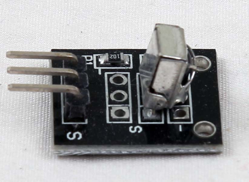 |
 |
https://tkkrlab.nl/wiki/Arduino_KY-022_Infrared_sensor_receiver_module | ||
| 23 | KY-023 XY-axis joystick module | 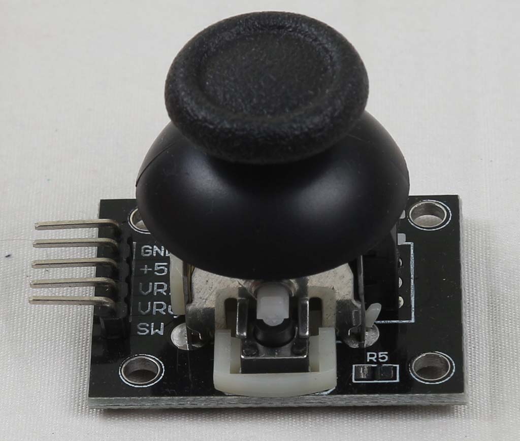 |
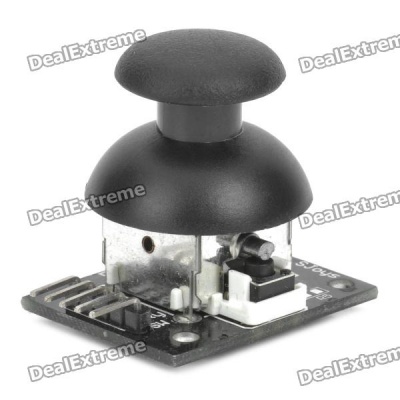 |
https://tkkrlab.nl/wiki/Arduino_KY-023_XY-axis_joystick_module | ||
| 24 | KY-024 Linear magnetic Hall sensors | 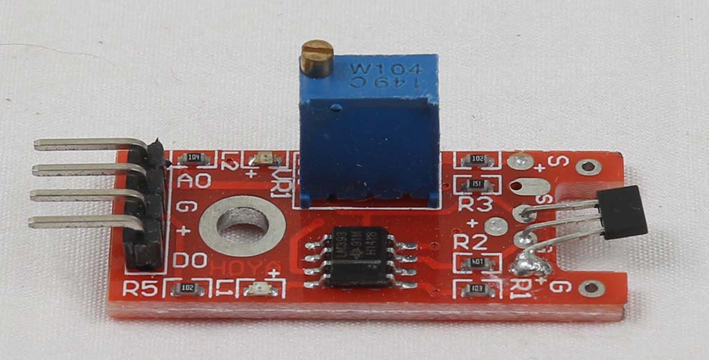 |
 |
https://tkkrlab.nl/wiki/Arduino_KY-024_Linear_magnetic_Hall_sensors | ||
| 25 | KY-025 Reed module | 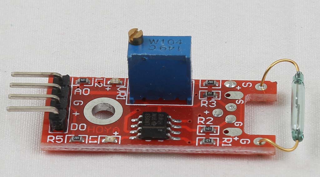 |
 |
https://tkkrlab.nl/wiki/Arduino_KY-025_Reed_module | ||
| 26 | KY-026 Flame sensor module | 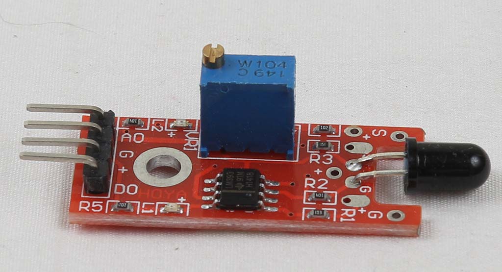 |
 |
https://tkkrlab.nl/wiki/Arduino_KY-026_Flame_sensor_module | ||
| 27 | KY-027 Magic light cup module | KY027:Magic LED cup Module |  |
 |
https://tkkrlab.nl/wiki/Arduino_KY-027_Magic_light_cup_module | |
| 28 | KY-028 Temperature sensor module | 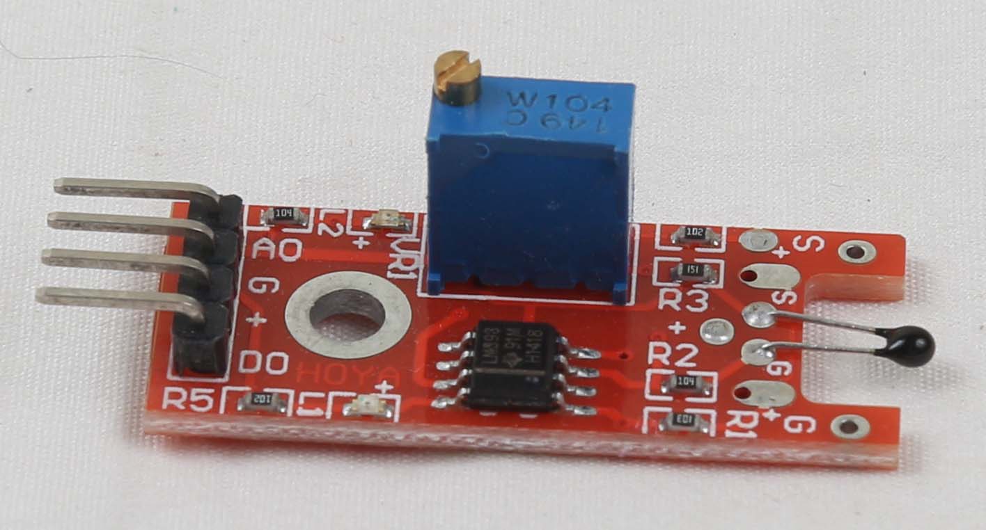 |
 |
https://tkkrlab.nl/wiki/Arduino_KY-028_Temperature_sensor_module | 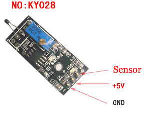 |
|
| 29 | KY-029 Yin Yi 2-color LED module 3MM | 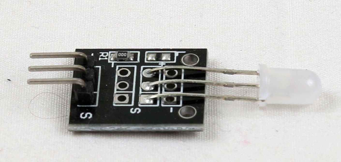 |
 |
https://tkkrlab.nl/wiki/Arduino_KY-029_Yin_Yi_2-color_LED_module_3MM | ||
| 30 | ||||||
| 31 | KY-031 Sensor module | KY031:Shock Sensor Module | 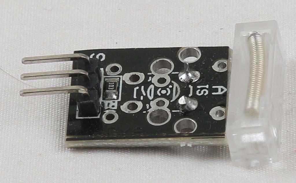 |
 |
https://tkkrlab.nl/wiki/Arduino_KY-031_Sensor_module | |
| 32 | KY-032 Obstacle avoidance sensor module | 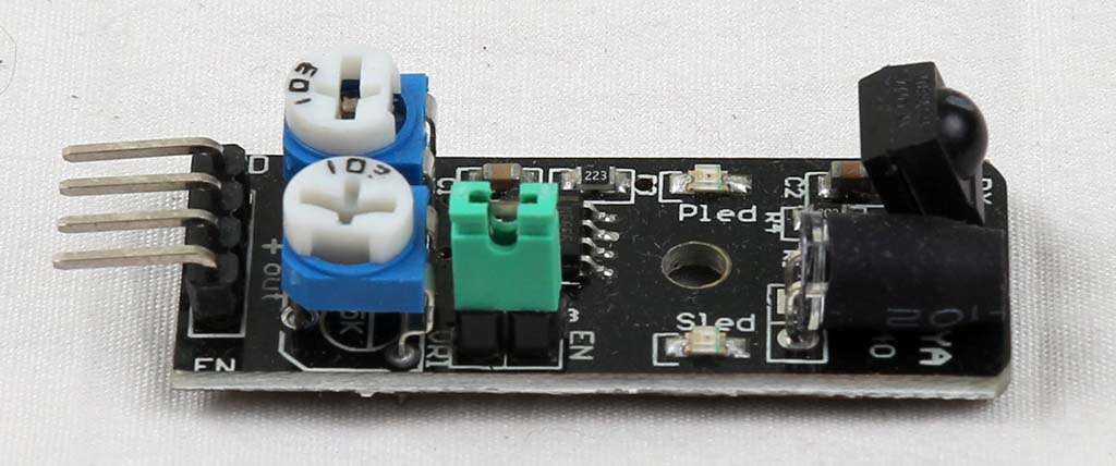 |
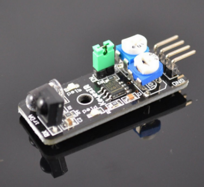 |
https://tkkrlab.nl/wiki/Arduino_KY-032_Obstacle_avoidance_sensor_module | ||
| 33 | KY-033 Hunt sensor module | KY033:Line follow Sensor Module | 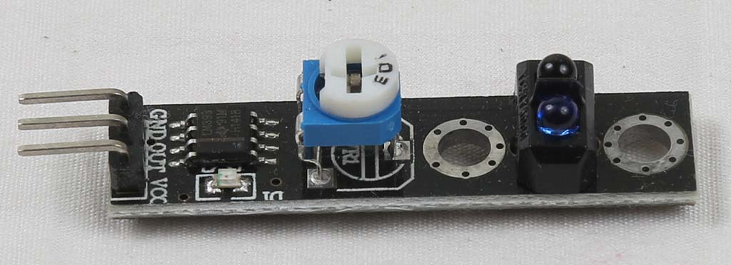 |
 |
https://tkkrlab.nl/wiki/Arduino_KY-033_Hunt_sensor_module | |
| 34 | KY-034 Automatic flashing colorful LED module |  |
https://tkkrlab.nl/wiki/Arduino_KY-034_Automatic_flashing_colorful_LED_module | |||
| 35 | KY-035 Class Bihor magnetic sensor | 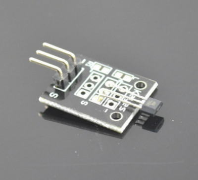 |
https://tkkrlab.nl/wiki/Arduino_KY-035_Class_Bihor_magnetic_sensor | 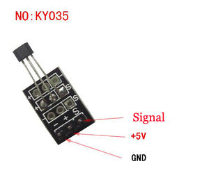 |
||
| 36 | KY-036 Metal touch sensor module |  |
 |
https://tkkrlab.nl/wiki/Arduino_KY-036_Metal_touch_sensor_module | ||
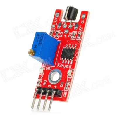
| 37 | KY-037 Sensitive microphone sensor module |  |
https://tkkrlab.nl/wiki/Arduino_KY-037_Sensitive_microphone_sensor_module | |||
| 38 | KY-038 Microphone sound sensor module | 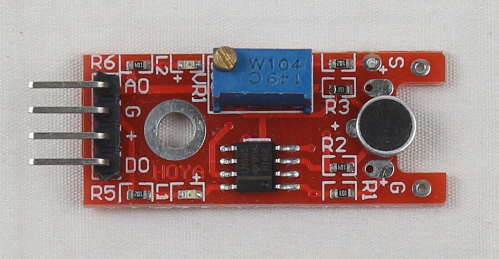 |
https://tkkrlab.nl/wiki/Arduino_KY-038_Microphone_sound_sensor_module | |||
| 39 | KY-039 Detect the heartbeat module | 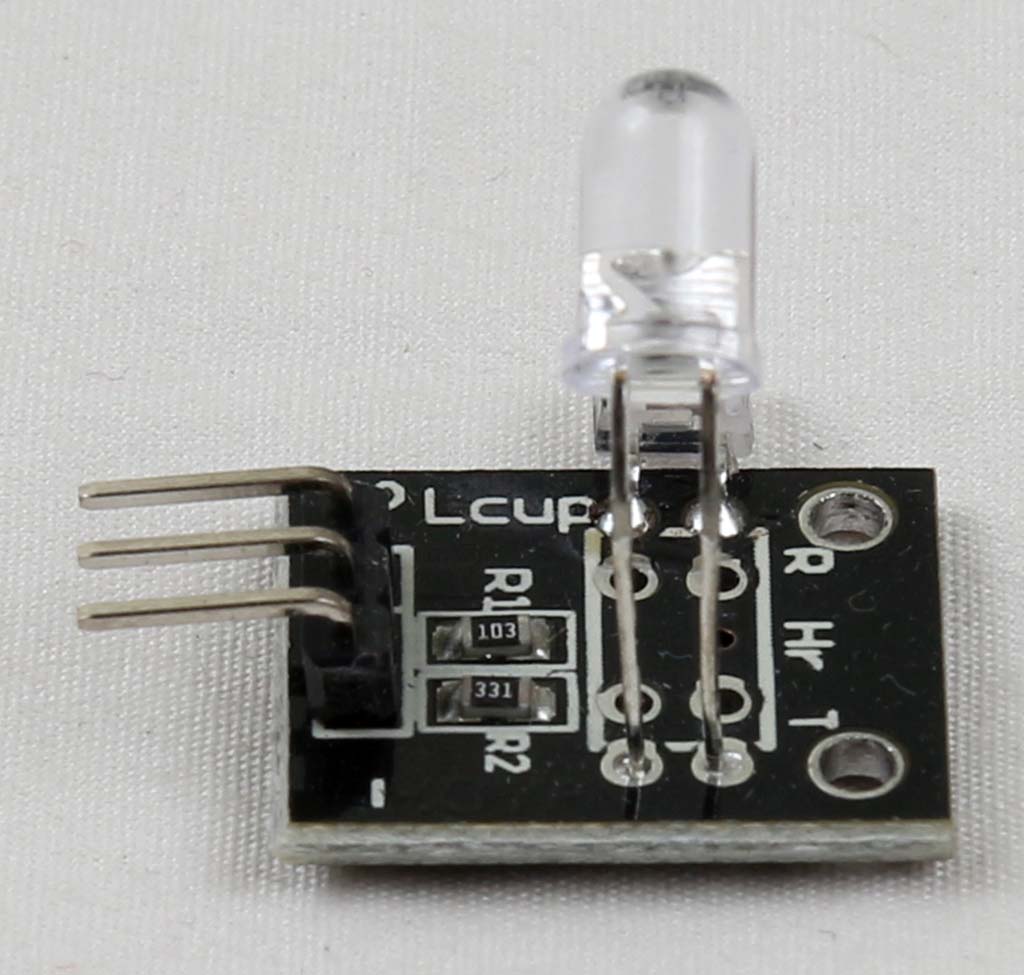 |
 |
https://tkkrlab.nl/wiki/Arduino_KY-039_Detect_the_heartbeat_module | ||
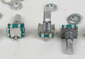
| 40 | KY-040 Rotary encoder module | 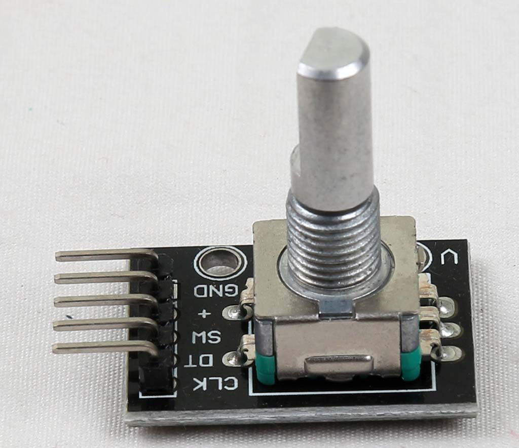 |
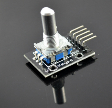 |
https://tkkrlab.nl/wiki/Arduino_KY-040_Rotary_encoder_module | ||
KY-001 Temperature sensor module
https://tkkrlab.nl/wiki/Arduino_KY-001_Temperature_sensor_module
Sumber:
- Advanced Sensors Kit for Arduino http://www.linksprite.com/wiki/index.php5?title=Advanced_Sensors_Kit_for_Arduino
- https://tkkrlab.nl/wiki/Arduino_37_sensors
- Manual dalam bahasa Cina https://github.com/josejuansanchez/37-in-1-arduino-sensor-kit


