 MPU-6050 akselerometer dan gyro
  MPU-6050 akselerometer dan gyro
Description:
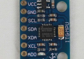
- Name: MPU-6050 module (three-axis gyroscope + triaxial accelerometer)
- 2.54mm pin spacing
- MPU-6050 Accelerometer + Gyro
- The MPU-6050 sensor contains a MEMS accelerometer and a MEMS gyro in a single chip. It is very accurate, since it contains 16-bits analog to digital conversion hardware for each channel. Therefore it captures the x, y, and z channel at the same time.
Specification:
- 16 bit AD converter-chip, 16-bit data output
- Use Chip: MPU-6050
- Power supply :3-5v (internal low dropout regulator)
- Communication: IIC communication protocol standard
- Gyro Range: ± 250 500 1000 2000 ° / s
- Acceleration range: ± 2 ± 4 ± 8 ± 16g
- Using Immersion Gold PCB, welding machines to ensure quality
- Size: 2 x 1.6 x 0.1mm
Application:
- Motion sensing games
- Augmented Reality
- Electronic Image Stabilization (EIS: Electronic Image Stabilization)
- Optical Image Stabilization (OIS: Optical Image Stabilization)
- “Zero-touch” gestures User Interface
- Pedestrian navigation
- Gesture shortcuts
Market:
- Smart phone
- Tablet device
- Handheld games
- 3D remote controller
- Portable navigation devices
Merujuk ke artikel di Arduino, nampaknya board ini mirip dengan tipe GY-521. Berikut ini adalah skema rangkaian tersebut:
 Skema rangkaian GY-521 untuk MPU-6050
Penjelasan Rangkaian GY-521
This sensor board has a voltage regulator. When using 3.3V to the VCC the resulting voltage (after the onboard voltage regulator) might be too low for a good working I2C bus. It is preferred to apply 5V to the VCC pin of the sensor board. The board has pull-up resistors on the I2C-bus. The value of those pull-up resistors are sometimes 10k and sometimes 2k2. The 2k2 is rather low. If it is combined with other sensor board which have also pull-up resistors, the total pull-up impedance might be too low.
This schematic is hard to find, so here is a copy: http://playground.arduino.cc/uploads/Main/MPU6050-V1-SCH.jpg
This part is designed in Fritzing: http://fritzing.org/projects/mpu-6050-board-gy-521-acelerometro-y-giroscopio
This schematic is hard to find, so here is a copy: http://playground.arduino.cc/uploads/Main/MPU6050-V1-SCH.jpg
This part is designed in Fritzing: http://fritzing.org/projects/mpu-6050-board-gy-521-acelerometro-y-giroscopio
A data visualiser that makes life easier when starting out. Also includes an extended version (By http://www.geekmomprojects.com/) of Kordal’s code. On Github https://github.com/janaka/Gy521-Dev-Kit
Referensi
- Sumber: Banggood: 6DOF MPU-6050 3 Axis Gyro With Accelerometer Sensor Module
- Datasheet dari InvenSense: http://www.invensense.com/products/motion-tracking/6-axis/mpu-6050/
- Produk serupa dari SparkFun: https://www.sparkfun.com/products/11028
- MPU 6050 dengan Arduino http://playground.arduino.cc/Main/MPU-6050