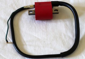
Koil racing Choho ini aslinya adalah untuk dipakai di motor sebagai pembangkit tegangan tinggi untuk busi.


Barang ini rencananya akan dipakai sebagai pembangkit tegangan tinggi (>12 kV) untuk beberapa percobaan.a
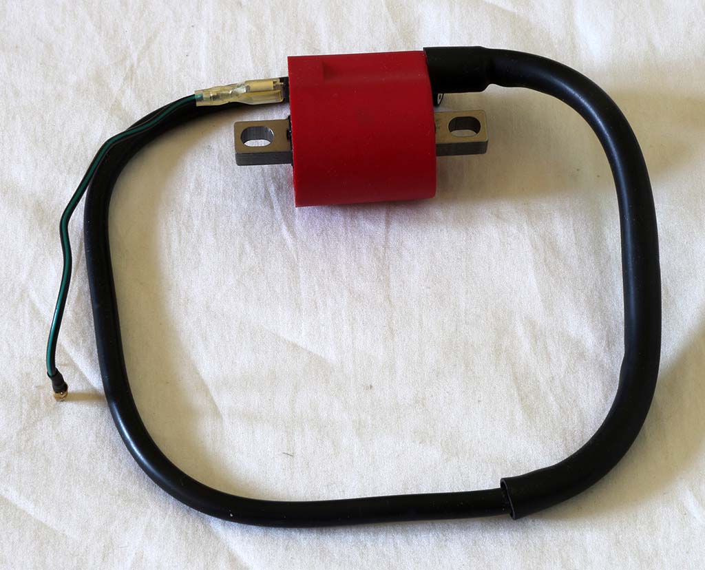
Koil racing Choho ini aslinya adalah untuk dipakai di motor sebagai pembangkit tegangan tinggi untuk busi.
Barang ini rencananya akan dipakai sebagai pembangkit tegangan tinggi (>12 kV) untuk beberapa percobaan.a

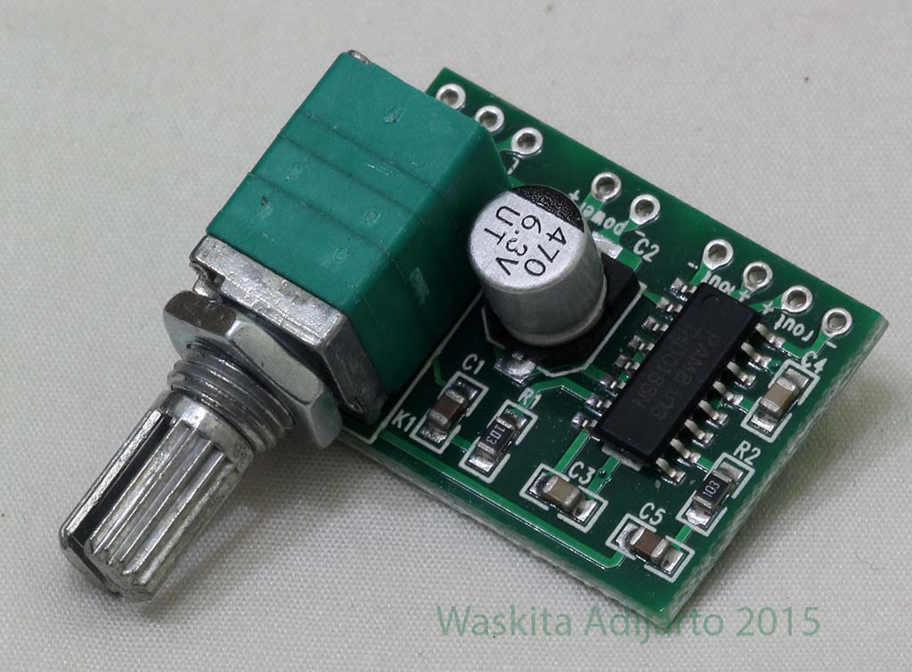
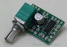
The PAM8403 is a 3W, class-D audio amplifier. It offers low THD+N,
allowing it to achieve high-quality sound reproduction. The new
filterless architecture allows the device to drive the speaker directly,
requiring no low-pass output filters, thus saving system cost and PCB
area.
With the same numbers of external components, the efficiency of the
PAM8403 is much better than that of Class-AB cousins. It can extend
the battery life, which makes it well-suited for portable applications.
The PAM8403 is available in SOP-16 package.

| Nomor Pin | Nama Pin | Fungsi |
| 1 | +OUT_L | Left Channel Positive Output |
| 2 | PGND | Power GND |
| 3 | -OUT_L | Left Channel Negative Output |
| 4 | PVDD | Power VDD |
| 5 | MUTE | Mute Control Input (active low) |
| 6 | VDD | Analog VDD |
| 7 | INL | Left Channel Input |
| 8 | VREF | Internal analog reference, connect a bypass capacitor from VREF to GND. |
| 9 | NC | No Connact |
| 10 | INR | Right Channel Input |
| 11 | GND | Analog GND |
| 12 | SHND | Shutdown Control Input (active low) |
| 13 | PVDD | Power VDD |
| 14 | -OUT_R | Right Channel Negative Output |
| 15 | PGND | Power GND |
| 16 | +OUT_R | Right Channel Positive Output |

Absolute Maximum Rating
These are stress ratings only and functional operation is not implied. Exposure to absolute maximum ratings for prolonged time periods may
affect device reliability. All voltages are with respect to ground.
| Parameter | Rating | Unit |
| Supply Voltage | 6.0 | V |
| Input Voltage | V -0.3 to VDD +0.3V | V |
| Operation Temperature Range | -40 to +85 | °C |
| Maximum Junction Temperature | 150 | °C |
| Operation Junction Temperature | -40 to +125 | °C |
| Storage Temperature | -65 to +150 | °C |
| Soldering Temperature | 300, 5 sec | °C |
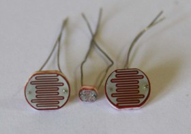
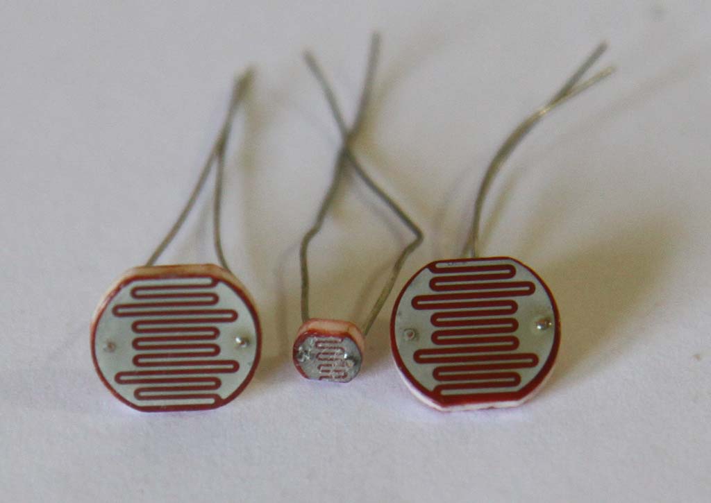
Light Dependent Resistor
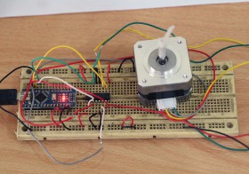
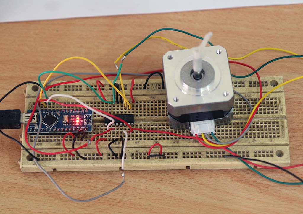
Berikut ini keterangan singkat mengenai motor stepper Casun tipe 42SHD0001. Tujuan utama motor ini adalah untuk pembuatan perangkat motorized slider otomatis.
Nema 17 Stepper Motor bipolar 4 leads 34mm 12V 0.4A 26Ncm(36.8oz.in) 3D printer motor 42SHD0001
This is the most popular Nema 17 model. It with 1.8°step angle (200 steps/revolution). Each phase draws current 0.4A at 12V, allowing for a holding torque of 26Ncm(36.8oz.in).
Normally , it use for Linear actuators and CNC router for plastic&metal .


Merek dan Model motor stepper ini ditulis di bagian belakang, namun untuk melihatnya agak susah karena tidak pakai tinta, kemungkinan digrafir dengan laser.


Percobaan motor stepper dengan prosesor Arduino Nano dan motor driver L293D. Dari hasil percobaan L293D berhasil dengan sukses menggerakkan motor stepper tersebut.
Untuk menyambungkan motor stepper ini ke perangkat lain dapat menggunakan pulley dan belt. Berikut ini pulley dengan poros 5 mm yang disambungkan ke motor stepper tersebut.

a
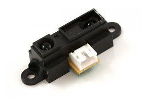
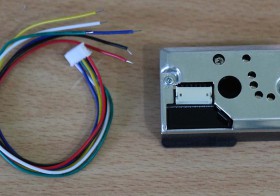
Berikut foto Sensor jarak Sharp GP2Y0A21YK
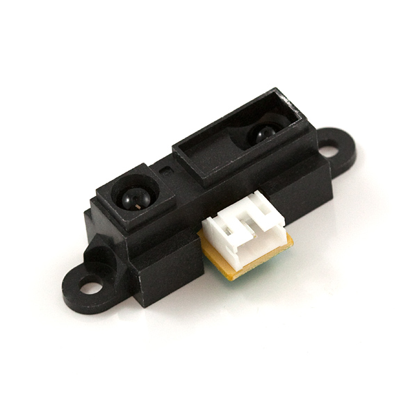
Penampakan barang sesungguhnya dari depan

Penampakan barang sesungguhnya dari belakang

Referensi
Sensor Jarak Infra Merah E18-D80NK
Another great infrared sensor. This infrared sensor can be powered with 5V and detection distance can be adjust from 3cm to 80cm with NPN output. It can be used at automation machine, mobile robot for obstacle detecting. The sensor provides a non-contact detection.
The implementations of modulated IR signal immune the sensor to the interferences caused by the normal light of a light bulb or the sun light.
Specification:
Connection:
Tutorial:
Referensi:

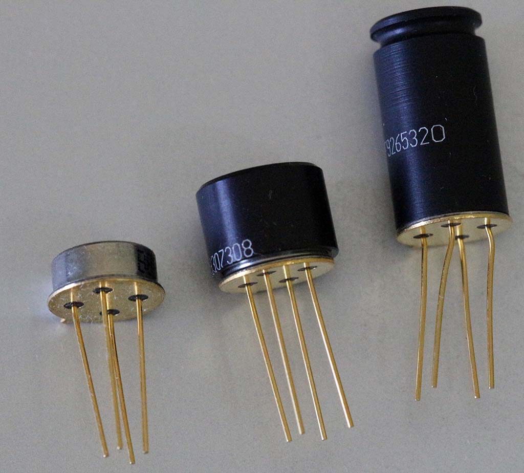


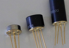
The MLX90614 is an Infra Red thermometer for non contact temperature measurements. Both the IR sensitive thermopile detector chip and the signal conditioning ASIC are integrated in the same TO-39 can.
Integrated into the MLX90614 are a low noise amplifier, 17-bit ADC and powerful DSP unit thus achieving high accuracy and resolution of the thermometer.
The thermometer comes factory calibrated with a digital SMBus output giving full access to the measured temperature in the complete temperature range(s) with a resolution of 0.02°C.
The user can configure the digital output to be PWM. As a standard, the 10-bit PWM is configured to continuously transmit the measured temperature in range of -20 to 120 °C, with an output resolution of 0.14 °C.
Penampakan kardus bagian depan

Penampakan kardus bagian belakang

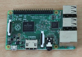
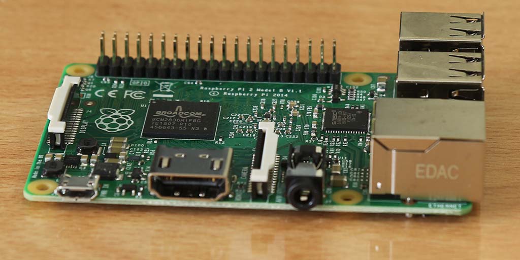
Penampakan board dari samping. Nampak konektor HDMI untuk output ke video.
Penampakan bagian atas. Nampak 2 IC besar, yang besar dari Broadcom, sedang yang kecil dari SMSC.
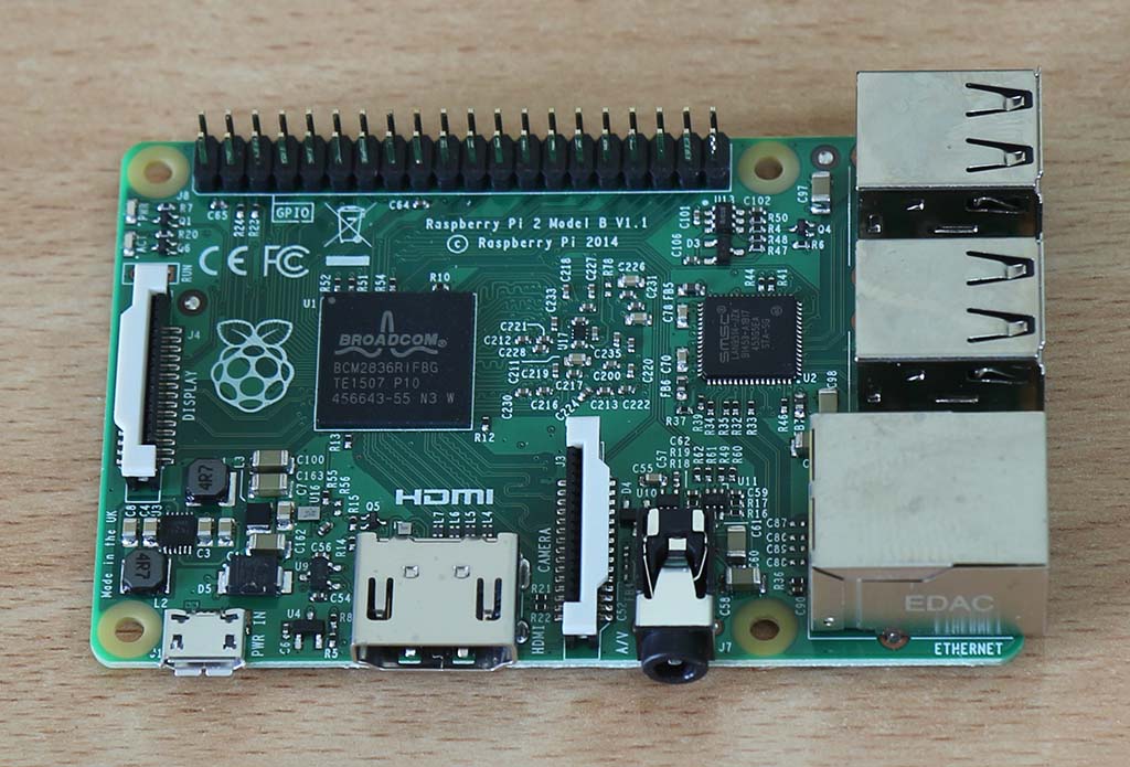
Di bagian bawah ada 1 IC besar, dengan tulisan ELPIDA.

Berikut beberapa penampakan kotak akrilik untuk Raspberry PI 2

Kotak akrilik untuk Raspberry Pi 2 model B

Manual yang diberikan cukup ringkas, karena detailnya semua mesti diakses lewat internet.


Ref:
Spesifikasi
Ref:

Manual


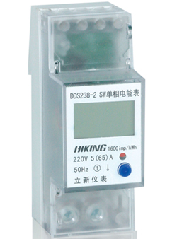

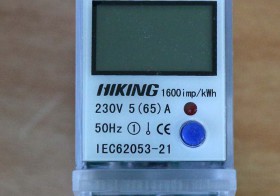
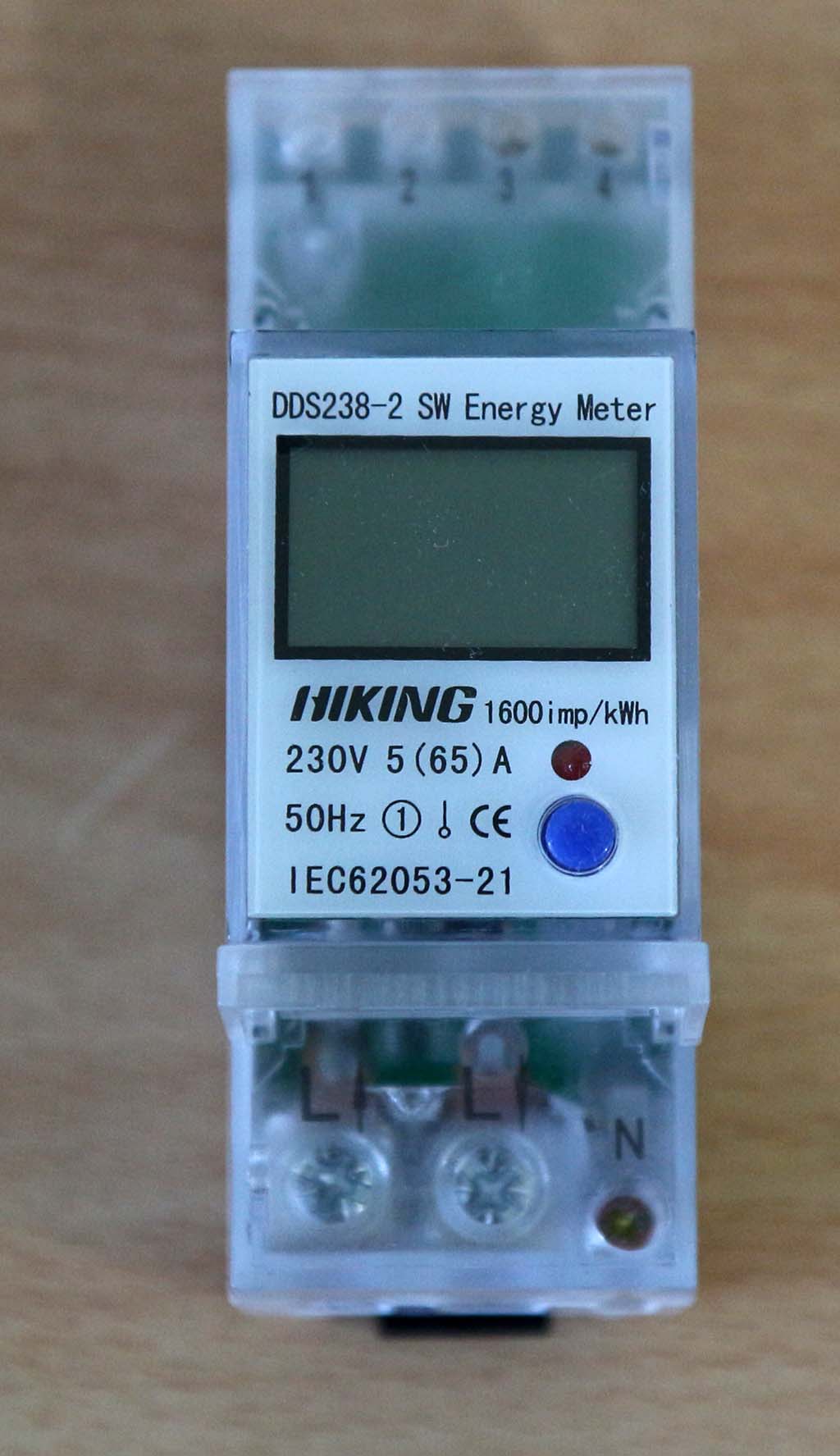
The DDS238-2 SW single phase electricity meter is designed to measure single phase two-wire AC active energy and variable parameter. All of its functions meet the technical requirement for class 1 single phase watt hour meter by the standard of IEC61036. The durable meter is high in stability and overload capability, low in power loss and small in volume.
Basic Function
1. The single phase electricity meter can measure bi-directional total active energy, as well as the reverse active energy in the total active energy.
2. Its LCD display is available with backlighting.
3. The meter displays realtime voltage, current, power, frequency and power factor.
4. Pulse LED indicator is available to indicate the operation status of meter, and pulse output comes with optical coupling isolation.
5. The product adopts 35mm DIN-rail installation
Optional Function
1. The meter can measure and display the total forward/reverse active energy.
2. Energy-reset function: Under energy-reset mode, the display of total energy display won’t be affected.
Technical Data
| Rated voltage | 110V, 120V, 220V, 230V, 240V |
| Working voltage range | 0.8~1.2Un |
| Rated current | 5(65)A, 5(30)A, 10(40)A, 5(60)A or other as required |
| Rated Frequency | 50Hz or 60Hz |
| Connection mode | Direct type |
| Display | LCD |
| Accuracy class | Class 1 |
| Power consumption | <2W/10VA |
| Start current | 0.004Ib |
| Constant | 800~3200 IMP/KWh |
| Pulse output | Passive pulse, pulse width is 80+5 ms |
| Executive standard | IEC62053-21, DL/T645-2007 or MODBUS-RTU |
| Working temperature | -30℃~70℃ |
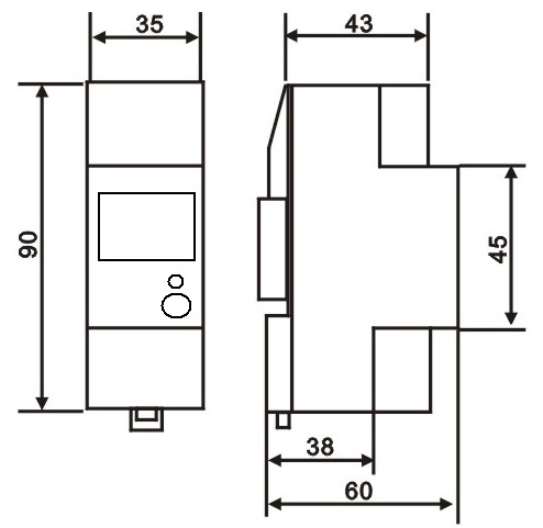
| Outline dimension LXMXH | 90×35×60mm |
| Weight | Approx 0.13kg |
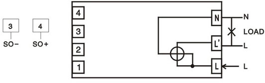
Wire connection
Outline dimension


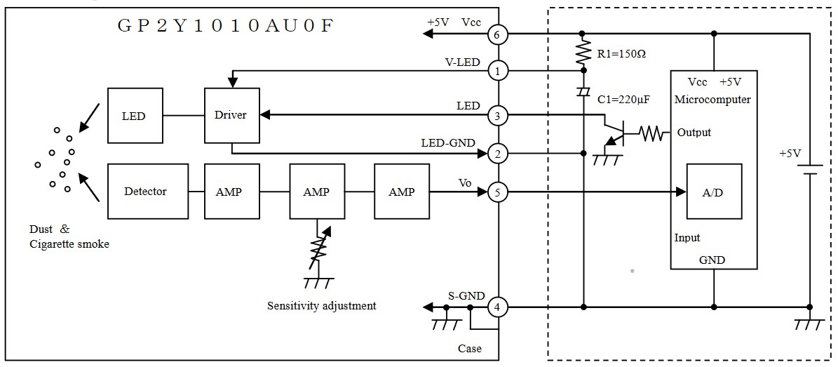
Ide rangkaian (sumber: Application note of Sharp dust sensor GP2Y1010AU0 :
Berikut ini contoh software ESP32 untuk membaca data dari sensor
Konfigurasi:
#define LED_SENSOR 23
#define ADC_INPUT 34
int sensorValue = 0;        // value read from the pot
int outputValue = 0;        // value output to the PWM (analog out)

void setup() {
  // initialize serial communications at 9600 bps:
  Serial.begin(115200);
  pinMode(LED_SENSOR, OUTPUT);
}

void loop() {
  // read the analog in value:
  digitalWrite(LED_SENSOR, HIGH);
  delayMicroseconds(280);
  sensorValue = analogRead(ADC_INPUT); // measurement 280 us after signal start
  delayMicroseconds(40); // total signal duration 320 us
  digitalWrite(LED_SENSOR, LOW); // turn off LED

  // print the results to the Serial Monitor:
  Serial.print("sensor = ");
  Serial.println(sensorValue);
  delay(1000);
}
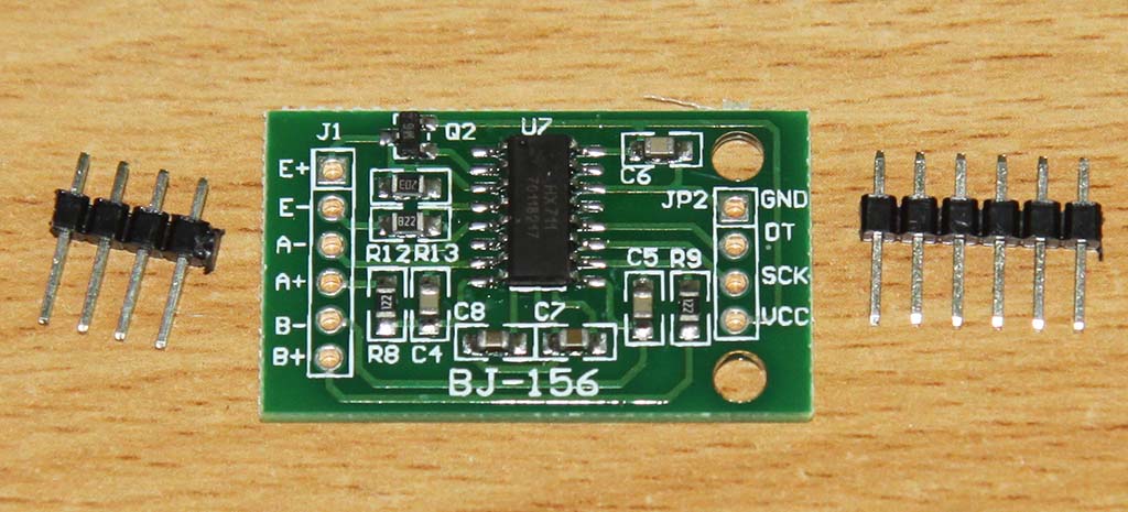
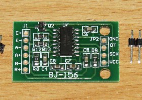
HX711 is an electronic scale module, whose working principle is to convert the measured changes in resistance value changes, through the conversion circuit into electrical output. The module communicates with the host computer through TTL 232.
Simple structure, easy to use, stable and reliable performance, high sensitivity and measurement speed and so on.
Widely used in aerospace, mechanical, electrical, chemical, construction, medicine and many other fields, used to measure force, pressure, displacement, strain, torque, acceleration.
Manual:
Ref
Download
HX711 ini cocok dirancang untuk aplikasi load cell, seperti
Arduino Library for HX711:
Pengukuran Detak Jantung dengan sensor yang dibahas di artikel Sensor Detak Jantung
Data mentah, delimited dengan semicolon:
Interval sampling adalah 1 ms
Board yang dipakai adalah Arduino Nano V3 clone
Software yang dipakai adalah Arduino sebagai berikut:
/*
Sumber: http://www.arduino.cc/en/Tutorial/BlinkWithoutDelay
*/// constants won’t change. Used here to set a pin number :
const int ledPin = 13; // the number of the LED pin
// Variables will change :
int ledState = LOW; // ledState used to set the LED
// Generally, you shuould use “unsigned long” for variables that hold time
// The value will quickly become too large for an int to store
unsigned long previousMillis = 0; // will store last time LED was updated
// constants won’t change :
const long interval = 1; // interval at which to blink (milliseconds)
unsigned long counter=0;
int sensorPin = A0; // select the input pin for the potentiometer
int sensorValue = 0; // variable to store the value coming from the sensor
void setup() {
// set the digital pin as output:
pinMode(ledPin, OUTPUT);
Serial.begin(115200);
}void loop()
{
// here is where you’d put code that needs to be running all the time.// check to see if it’s time to blink the LED; that is, if the
// difference between the current time and last time you blinked
// the LED is bigger than the interval at which you want to
// blink the LED.
unsigned long currentMillis = millis();if(currentMillis – previousMillis >= interval) {
// save the last time you blinked the LED
previousMillis = currentMillis;
// set the LED with the ledState of the variable:
digitalWrite(ledPin, ledState);
counter++;
sensorValue = analogRead(sensorPin);
Serial.print(counter);
Serial.print(“;”);
Serial.println(sensorValue);}
}
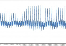
Grafik hasil pengukuran (sekitar 30000 sampel pertama). Nampak amplitude maksimum berubah-ubah, tergantung posisi dan tekanan jari pada sensor.
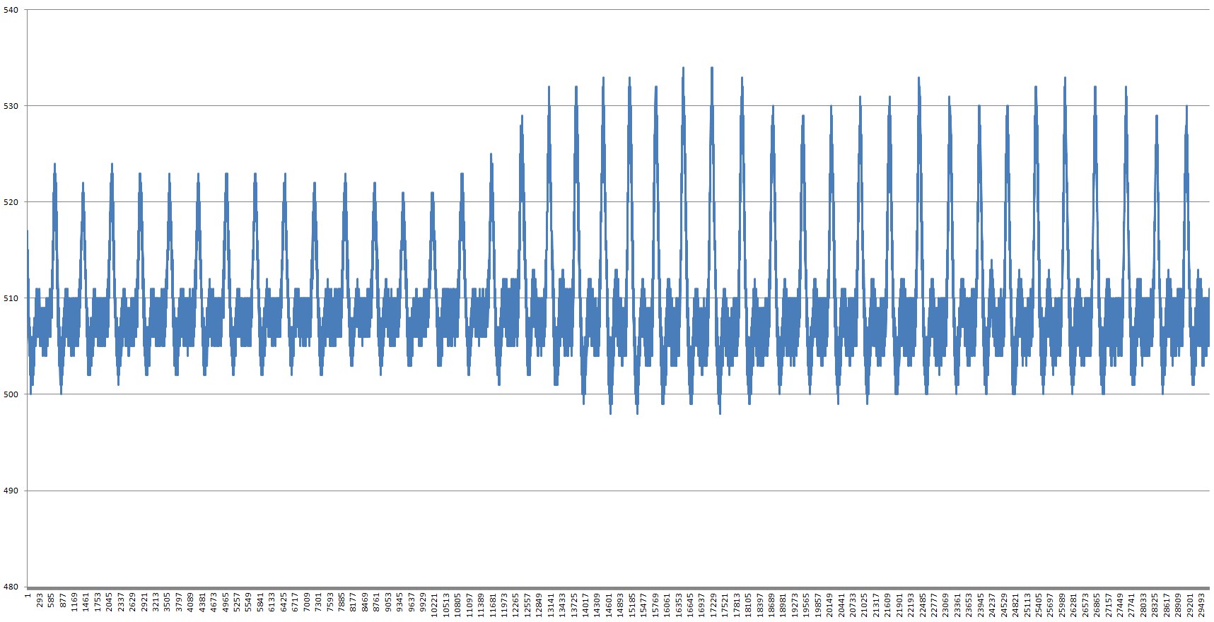
Grafik hasil pengukuran (hanya sekitar 1000 sampel pertama saja). Nampak ada noise pada hasil pengukuran.

Rentang angka ADC adalah 0 sampai 1023 (ADC 10 bit di ATMega328)
Angka maksimum yang tercatat adalah 536. Angka minimum yang tercatat adalah 496. Rentang angka yang tercatat adalah 40. Hal ini konsisten dengan hasil tampilan dengan software Processing di artikel Sensor Detak Jantung yang menunjukkan rentang angka pengukuran sempit dibandingkan dengan sensor asli.

Data mentah:
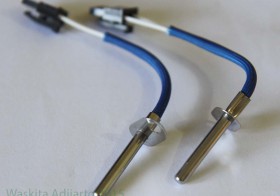
Berikut ini adalah sensor temperatur NTC K524 yang ditemukan di Jaya Plaza. Harganya lumayan murah, di bawah Rp 10 ribu.
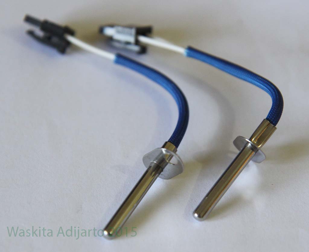
Pengukuran di temperatur 24 derajat Celcius menghasilkan resistansi 41.6 ohm.
Sensor dihangatkan dengan cara digenggam dengan tangan, hasilnya resistansi turun ke 33 ohm. Temperatur tangan kira-kira sekitar 35 derajat celcius menurut termometer GM320.
Spesifikasi NTC K524 menurut http://en.tdk.eu/tdk-en/176900/products/application-guides/consumer—epcos-brand/home-appliances/ignition-units-for-gas-cookers/ntc-thermistors adalah sebagai berikut:
Sensor ini non-linier, sehingga untuk konversi resistansi ke temperatur akan memerlukan software khusus. Cocok untuk percobaan dengan board Arduino Nano.
Catatan:
Referensi:
Penampilan luar kemasan Dekko

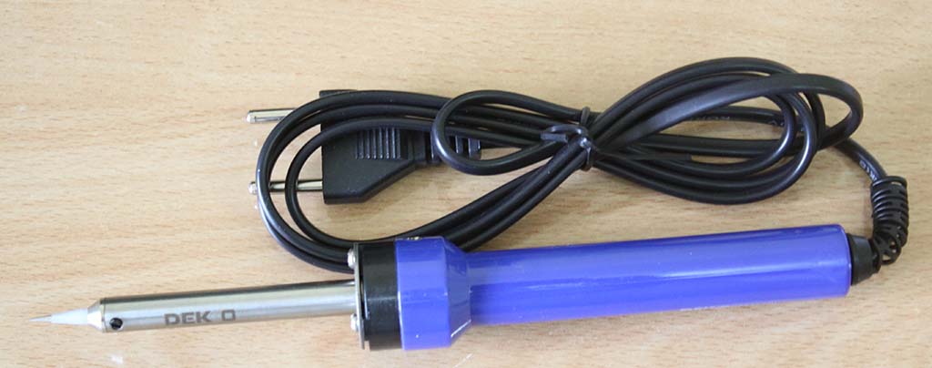
Mata soldernya runcing, cocok untuk menyolder komponen kecil seperti SMD


Manual Dekko DCS30 terdapat di karton kemasannya


WATTAGE AND APPLICATION
| 20 40W | 60 80W | Above 100W |
| P.C. BoardI.C. Transistor
Chip Conden&or |
Electric PartsSwitch, Connector
Transformer |
When a large heat capacity is required |
HOW TO SOLDER
a
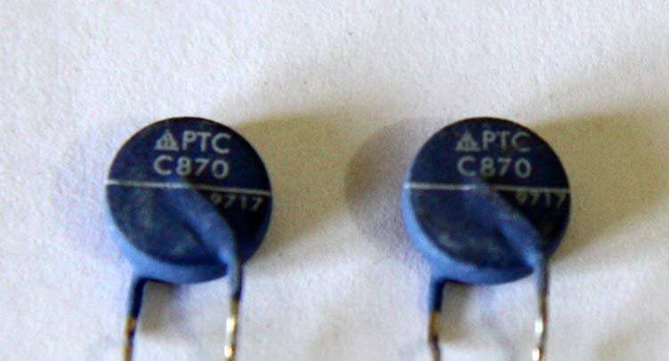
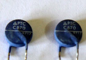
C870 ini adalah sebuah sensor temperatur PTC (Positive Temperature Coefficient), artinya makin panas maka makin besar resistansinya. Menurut datasheetnya, komponen ini umumnya dipakai sebagai pembatas arus. Mekanismenya adalah arus pada PTC menghasilkan panas, dan panas ini akan menaikkan nilai resistansinya. Jika nilai resistansi tinggi, maka arus yang mengalir akan berkurang.
Referensi:
PTC_OC_Leaded_230V_C_B598_C810_C890
CAUTION
When the power is on, the tip temperature can reach over 300°C CS72°F). Since mishandling may lead to burns or fire, be sure to comply with the following precautions.
WARNING
DAYA DAN APLIKASI
CARA MENYODER
PERHATIAN
Ketika solder on, ujung solder bisa mencapai temperatur lebih dari 300°C (572*F). Penanganan
yang salah bisa menyebabkan luka bakar dan kebakaran, perhatikan hal-hal berikut:
PERINGATAN