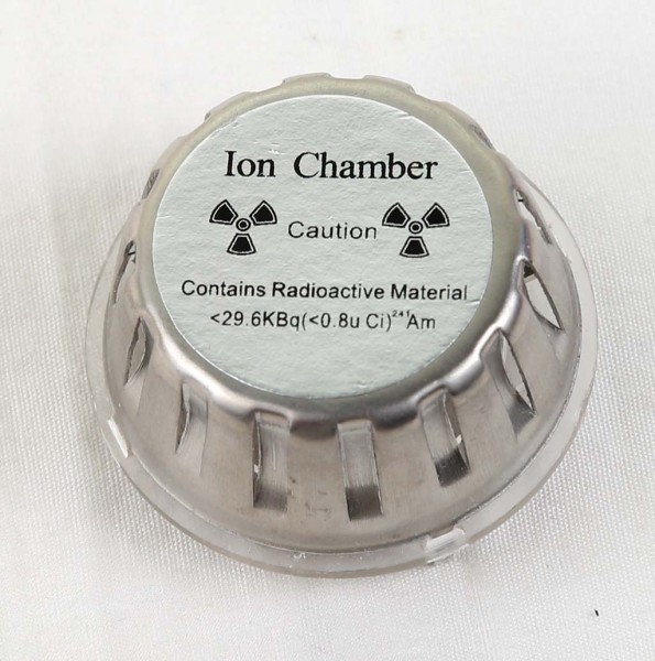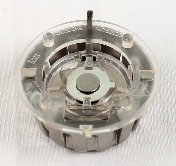

Fungsi utama sensor ini tentunya adalah untuk mendeteksi adanya asap di udara. Namun karena di dalamnya mengandung Americium yang radioaktif, sensor ini berguna juga sebagai sumber radiasi untuk menguji sensor radiasi geiger counter.
Product description:
1) Ionization source characteristics and radiation safety performance:
2) The ionization chamber fitted with a high performance and low activity of Am-241 ionization
3) Ionization source activity: 0.5uCi ( 18KBq ) 0.8uCi±10% ( 30KBq±10% )
4) Ionization source a spectroscopy: peak: 4.5MeV ± 10%, FW HM<0.7MeV
5) Safety grading standards ( GB4075, IS02919 ) C64444
6) Ionization chamber radiation dose rate at 25cm: 0.03mGy/ ( 1mGy value lower than population dose standard )
7) Ionization chamber specification, parameter:
8) Conditions: outer electrode and the source electrode voltage ( VDD supply voltage ): 9V
9) Environment temperature: 20 + C: close to atmospheric pressure standard atmospheric pressure, clean air
10) Collecting electrode equilibrium potential: 5.3~6.5V
11) Collecting electrode potential with the smoke concentration change
12) Light reduction rate was 1% feet: 0.6V
13) Light reduction rate was 4% feet: 2.2V
14) Insulator leakage current ( Max ): 0.5Pa
16) Capacitor ( collection of extreme outer electrode + to the source base ): 6.0pF
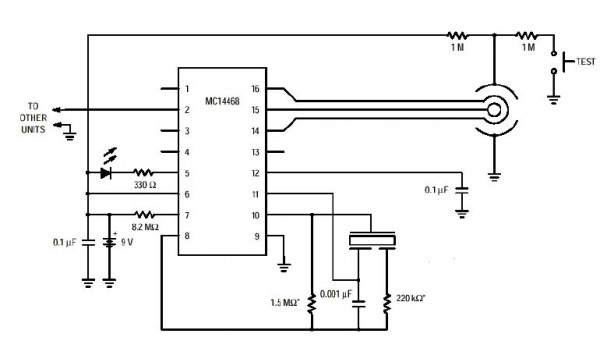
Cara kerjanya dapat dilihat di http://circuitcellar.com/wp-content/uploads/2012/06/CC2011110601.pdf
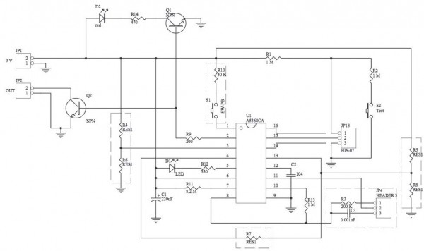
Contoh rangkaian: http://www.e-gizmo.com/KIT/images/smokesensor/Smoke%20Sensor%20Manual%20Rv0.pdf

Datasheet [EN]
Datasheet berikut diambil dari http://www.datasheet4u.com/datasheet/H/I/S/HIS-07_Hanwei.pdf.html
HANWEI ELECTRONICS CO.,LTD
http://www.hwsensor.com
HIS-07 SPECIFICATIONS
1. SCOPE:
This specification sheet is for ionization smoke chamber model HIS-07 (radiation source-0.5 microcurie Am-241, 2 chambers with a source, made in compliance with UL 217, EN-54-7) for applications to smoke detectors.
2. Radiation source:
Nuclide ; americium 241
Radioactivity;Ave.33.3 KBq. =0.9μ CI(29K~37KBq)
3.Operational conditions:
- Power supply; DC9V
- Operational ambient conditions;
- Temperature 0–50℃
- Humidity less than 95 (No dew condensation)
4.Maximum ratings:
Supply voltage; DC 24V
Operation; Temperature -10…+60℃ , Humidity less than 95%
Storage: Temperature -25…+80℃ , Humidity less than 95%
6.Shape,dimensions, weight;
Shape; As per attached drawing
Dimensions; 22.0×Ф 42mm
Weight; 12g.
7. Ratings:
Test conditions; at 25℃,60% RH
| Items | Specifications |
| Supply voltage | DC 9V |
| Current consumption | 27±3pA |
| Output voltage | 5.6±0.4 V in clean air |
| Sensitivity | 0.6 ± 0.1 V at 2%/foot of smoke |
(Tested according to UL 217)
8.Characteristics:
8-1.Sensitivity characteristics
Table 1 Test conditions ;at 25℃,60% RH
| Smoke concentration(%/foot) |
output | Variation (△V) |
| 0 | 5.6±0.4 | 0 |
| 1 | 5.3±0.5 | 0.3±0.1 |
| 2 | 5.0±0.5 | 0.6±0.1 |
| 3 | 4.7±0.5 | 0.9±0.2 |
| 4 | 4.4±0.5 | 1.2±0.2 |
| 5 | 4.2±0.5 | 1.4±0.2 |
Gray smoke test according to UL 217 Air velocity;0.16m/sec.
8-2. Supply voltage dependency
Table 2 Test conditions ;at 25℃,60% RH
| Supply voltage(V) | Output voltage(V) |
| 6 | 3.3±0.3 |
| 9 | 5.6±0.4 |
| 12 | 8.0±0.7 |
| 15 | 10.0±0.85 |
| 18 | 13.0±1.0 |
8-3 Temperature & Humidity dependency
Table 3 Temperature dependency
| Temperature(℃) | Output (V) |
| 0 | Output(V) 5.15±0.4 |
| 25 | 5.6±0.4 |
| 50 | 5.85±0.4 |
Table 3 Humidity dependency
| Humidity(%C) | Output (V) |
| 30 | 5.75±0.5 |
| 60 | 5.6±0.4 |
| 90 | 5.45±0.4 |
9.Durability tests;
9-1.Heat resistance test
| Test method | criteria |
| At +80 ℃ ± 5 ℃ for 72 hrs. Without electrified |
To maintain the characteristics shown in Heading No.8 after test .To show neither deforming, nor discoloring, nor cracks . |
9-2. Low temperature resistance
| Test method | criteria |
| At -30℃±5℃ for 72 hrs . without electrified |
To maintain the characteristics shown in Heading No.8 after test .To show neither deforming, nor discoloring, nor cracks . |
9-3.High humidity resistance
| Test method | criteria |
| At +40℃±5℃& 85 ±5% RH for 72 hrs . without electrified |
To maintain the characteristics shown in Heading No.8 after test .To show neither deforming, nor discoloring, nor cracks . |
9-4.Vibration test
| Test method | criteria |
| Vibrated with amplitude of 0.25mm at every 5Hz from 10 — 35Hz for 15 min . with sympathetic vibration. If no sympathetic vibration occurs, to be vibrated at 35Hz for 4 hour . |
To maintain the characteristics shown in Heading No.8 after test .To show neither deforming, nor discoloring, nor cracks . |
9-5.Impact test
| Test method | criteria |
| Dropped from a height of 1 m on to wooden plate with 3 different directions . | To maintain the characteristics shown in Heading No.8 after test .To show neither deforming, nor discoloring, nor cracks |
TEL:86-371-67169070 67169080
FAX:86 371 67169090
E-mail: [email protected]
10. Remarks
10.1 Output voltage is to be measured using an electrometer with more than 1014 of impedance or an exclusively designed measuring circuit with Ics . Normal testers with around 100MΩ impedance would be insufficient for measurement .
10.2 Upon assembling detectors ,attention is to be paid not to let a soldering flux get inside smoke chambers .If inside of the chambers is contaminated ,cleaning or washing is necessary .
10.3 The output lead wire of a chamber and an input terminal of a circuit must be connected in air to keep the connected point away from the surface of a PC board(usually a teflon pin is used to support the connected point) .Because of the resistance level of paper phenol PC boards , current leakage will occur on to the PC board . This will prevent to read correct outputs .
10.4 The connected point of the lead wire and the input terminal of an FET or an IC must be protected from humidity using a silicon resin or the like so that current leakage from the packages will be minimized .
10.5 Because of the necessity of reading a tiny current put out from the chamber ,this sensor must be electrically shielded to minimize noises from the outside .As the most sensitive part to noises is the connected part of the lead wire and the input the terminal of a circuit ,this part must definitely be shielded .

TEL:86-371-67169070 67169080
FAX:86 371 67169090
E-mail: [email protected]
Datasheet:
- http://www.datasheet4u.com/datasheet/H/I/S/HIS-07_Hanwei.pdf.html
- http://www.datasheet4u.com/PDF/634738/HIS-07.html
- http://us.100y.com.tw/pdf_file/HIS-07.pdf (Chinese)
- HIS-07 Manual (PDF)
