Salah satu metode membasmi nyamuk yang sering dipakai adalah dengan menggunakan raket pembasmi nyamuk. Raket ini menggunakan tegangan tinggi (beberapa ribu volt) untuk mematikan nyamuk yang lewat di raket tersebut.
Berikut ini beberapa hal ringan seputar raket pembasmi nyamuk.
Ukuran Dan Berat
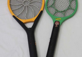
Raket pembasmi nyamuk terdapat dalam berbagai ukuran. Menurut saya yang paling penting adalah luas penampang raket dan berat raket. Makin luas penampang, maka makin mudah membidik nyamuk, karena tidak usah terlalu akurat. Makin ringan maka makin mudah mengayun raket untuk membidik nyamuk yang terbangnya zig-zag.
Rangkaian elektronik raket pembasmi nyamuk
Di dalam raket nyamuk ada rangkaian yang fungsinya membangkitkan tegangan ribuan volt dari batere yang hanya beberapa volt. Rangkaian elektronik nya rata-rata sederhana, detailnya dapat dibaca di artikel “Rangkaian Elektronika Raket Nyamuk”
Cas Jangan Terlalu Lama
Raket nyamuk rata-rata dapat diisi ulang baterenya. Namun rangkaian pengisi batere di dalam raket nyamuk sangat sederhana sehingga tidak ada perlindungan terhadap over-charge atau pengisian berlebihan. Jadi jika batere sudah penuh jangan lupa langsung dicopot dari jala-jala listrik.
Daya Bunuh Raket
Raket nyamuk kadang-kadang dapat mematikan nyamuk dalam 1 kali hantaman, kadang juga lebih. Dari pengalaman saya, jika nyamuknya gendut karena habis menghisap darah, maka nyamuk tersebut tidak langsung mati dalam 1 x hantaman, jadi biasanya jatuh namun masih hidup.
Raket Dapat Membakar Nyamuk
Jika ada nyamuk yang terkena raket kemudian tersangkut di dalam raket, maka jika dibiarkan nyamuk tersebut dapat gosong terbakar oleh arus listrik dan akhirnya dapat menjadi abu.
Raket Nyamuk Berisik
Raket nyamuk mengeluarkan suara ledakan keras ketika menghantam nyamuk. Ledakan ini berasal dari loncatan listrik tegangan tinggi ke nyamuk yang memanaskan udara secara mendadak, sehingga timbul gelombang suara. Prosesnya seperti terjadinya suara petir, hanya skalanya lebih kecil.
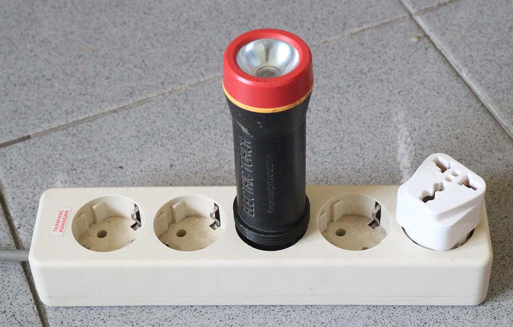
Raket Nyamuk Colokan Listriknya Macam-macam
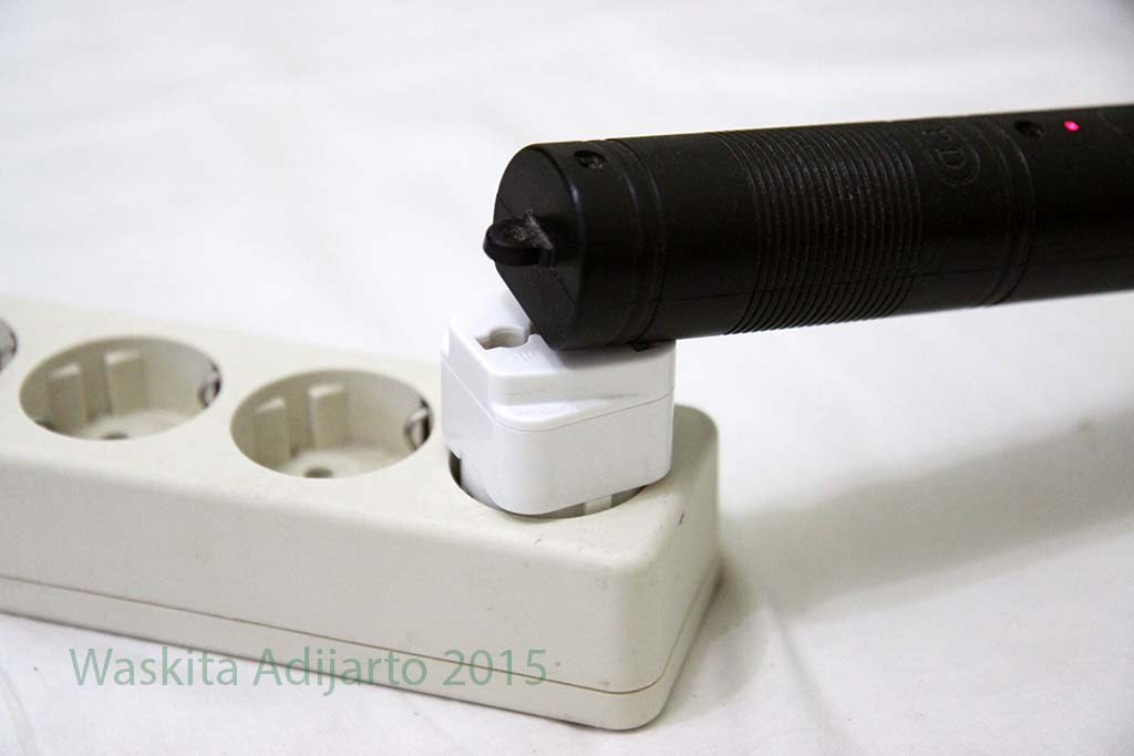
Raket nyamuk dapat dicas / diisi ulang dari jala-jala listrik. Namun perlu diperhatikan ada 2 macam raket nyamuk, ada yang dapat dimasukkan ke stop kontak yang dalam yang ada ground nya, ada juga colokannya pendek sehingga tidak dapat dimasukkan. Untuk yang colokannya pendek, hanya dapat dipasang di stop kontak yang datar, atau mesti pakai konverter supaya dapat dipasang di stop kontak yang dalam.
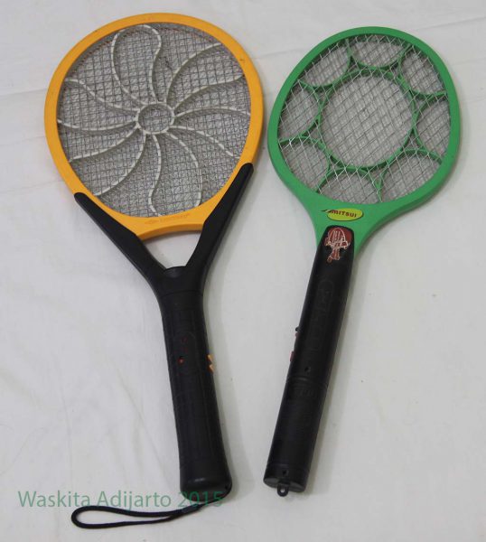
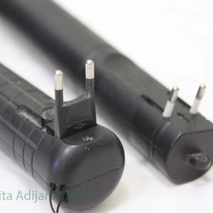
Berikut ini foto 2 macam colokan raket nyamuk, ada yang panjang dan ada yang pendek.
Colokan listrik raket nyamuk
Raket nyamuk dengan colokan yang panjang lebih mudah, karena dapat masuk ke stok kontak dengan lubang yang dalam.
Raket nyamuk dengan colokan panjang
Raket nyamuk dengan colokan yang pendek tidak dapat masuk ke stop kontak dengan lubang yang dalam, sehingga perlu ditambahkan alat lain agar dapat disambungkan.
Raket nyamuk dengan colokan pendek
Pembunuh Lalat
Raket pembunuh nyamuk ini juga dapat membunuh serangga terbang lain seperti lalat. Namun lalat ini agak susah mati kalau hanya dipukul sekali, biasanya kalau kena hanya jatuh saja, terus kalau dibiarkan akan terbang lagi seperti biasa.
Pada tulisan ini saya membongkar 3 buah raket nyamuk untuk mengetahui apa saja isi di dalam raket nyamuk tersebut. Tipe raket nyamuk yang dibongkar tidak jelas, yang jelas mereknya adalah Tecstar, Mitsui dan Shinyoku.
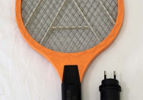
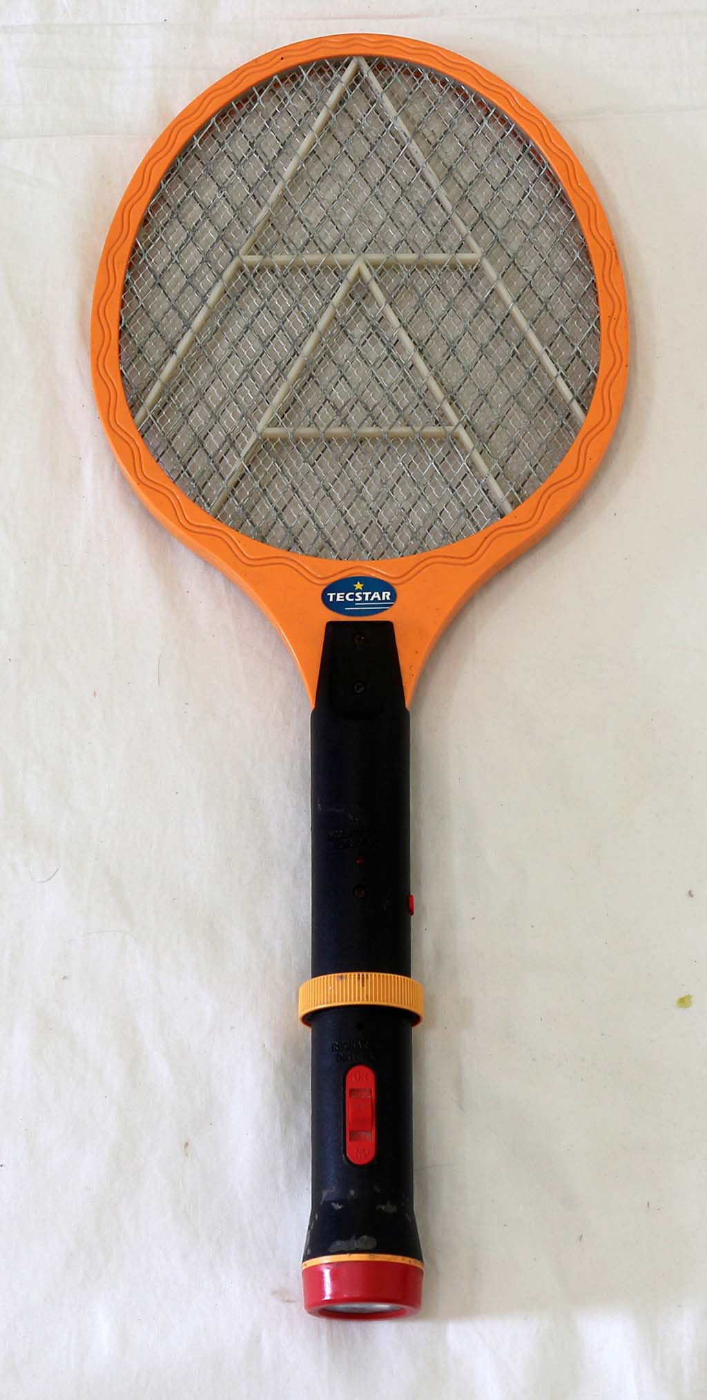
Raket Nyamuk Tecstar
Berikut ini hasil membongkar raket nyamuk merek Tecstar
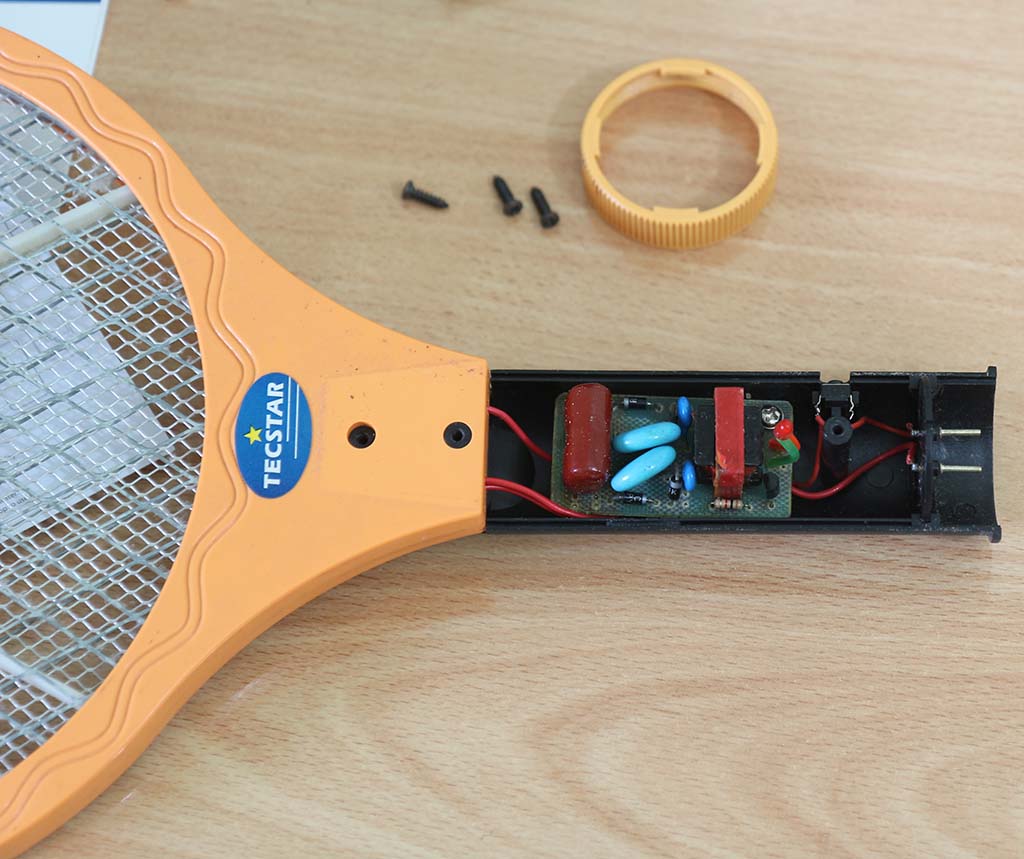
Raket nyamuk Tecstar
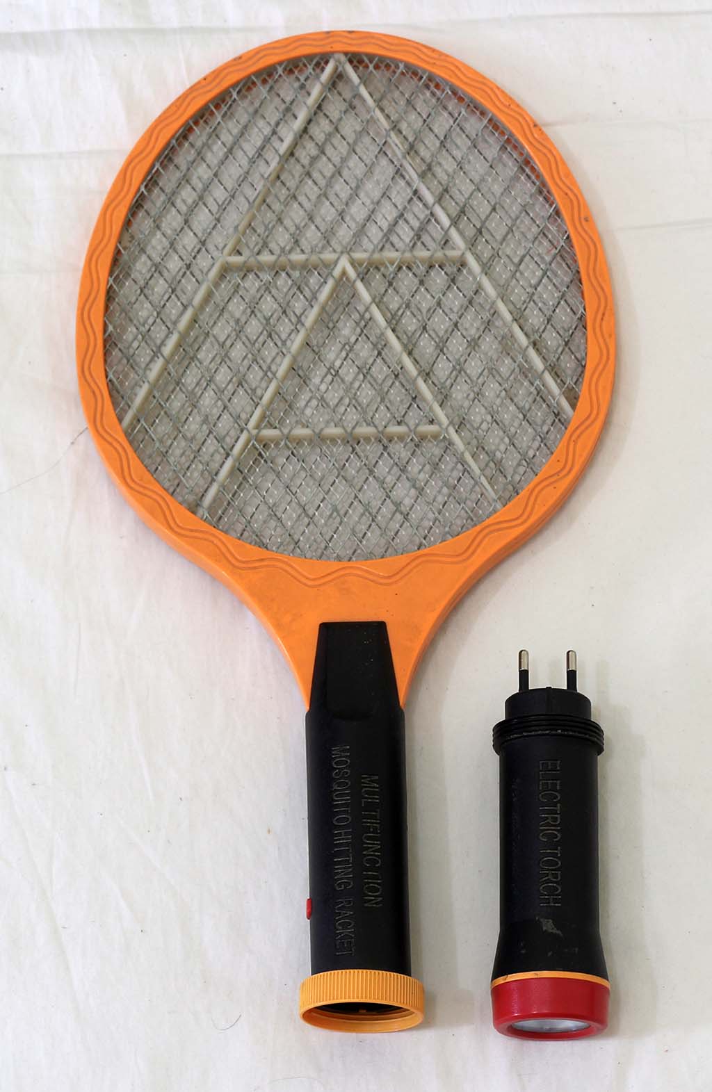
Raket nyamuk ini terdiri dari 2 potongan yaitu raket dan batere/charger. Untuk mengisi batere dilakukan dengan mencopot bagian batere.
Raket nyamuk Tecstar
Cara membongkarnya cukup mudah dengan mencopot beberapa buah sekrup yang terlihat jelas.
Raket nyamuk Tecstar
Pada gambar di atas nampak rangkaian utama raket nyamuk tersebut.
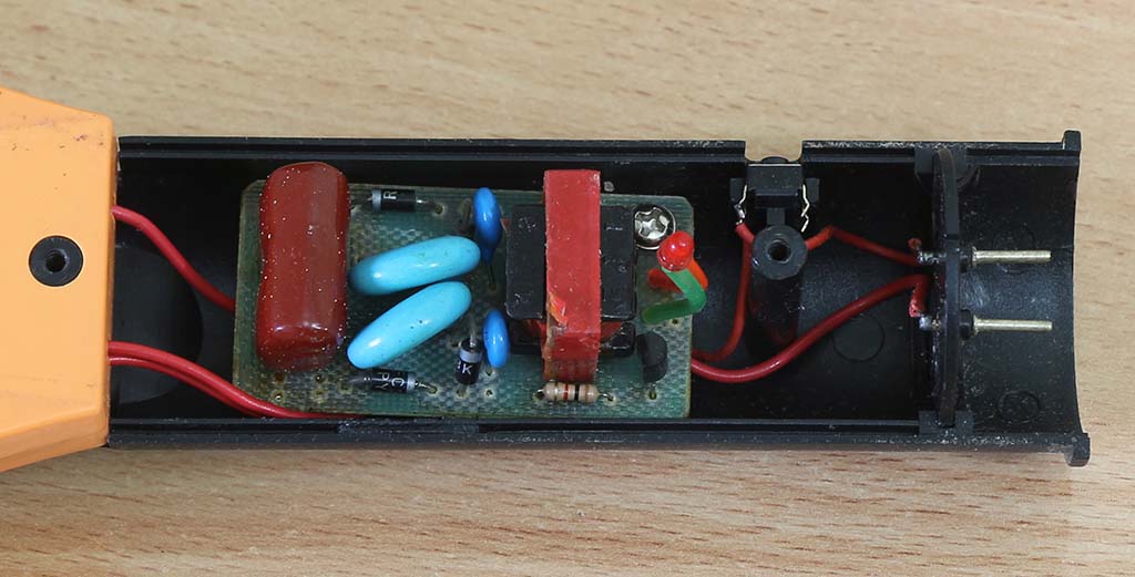
Berikut ini rangkaian dilihat dari jarak dekat.
Raket nyamuk Tecstar
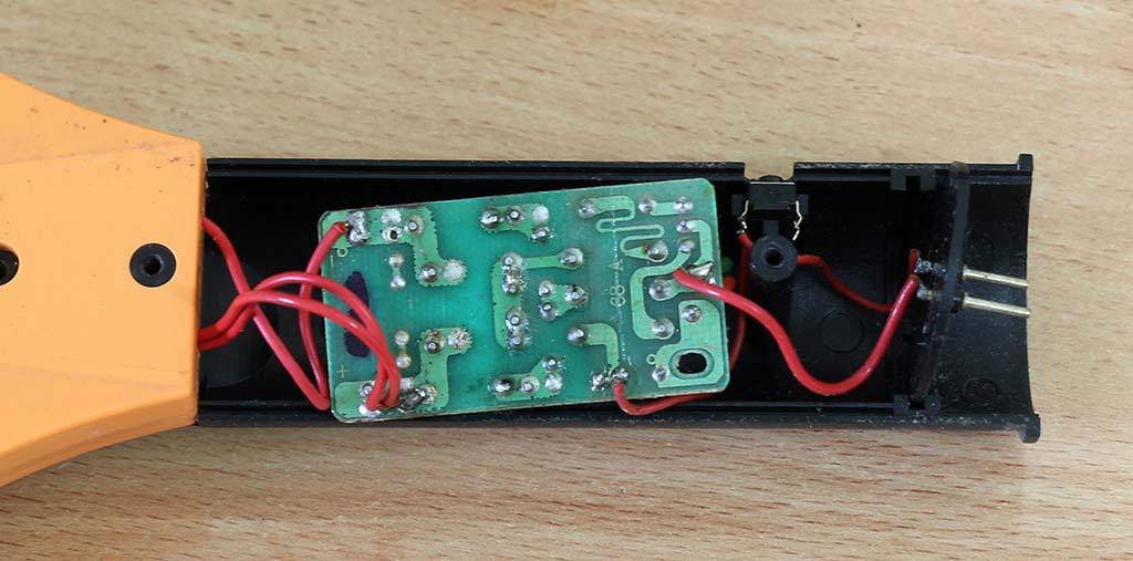
Berikut ini papan rangkaian bagian bawah. Rangkaian ini cukup sederhana hanya memerlukan PCB 1 layer saja.
Raket nyamuk Tecstar
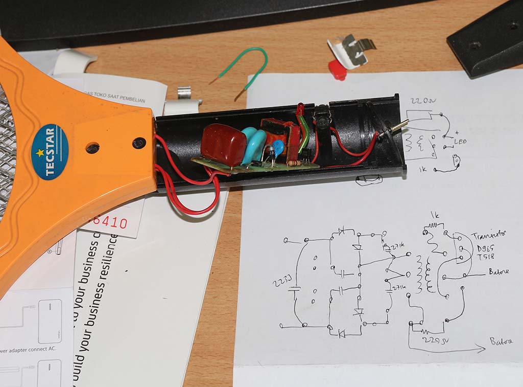
Selanjutnya mencoba menganalisis rangkaian di dalamnya.
Raket nyamuk Tecstar: batere dan charger
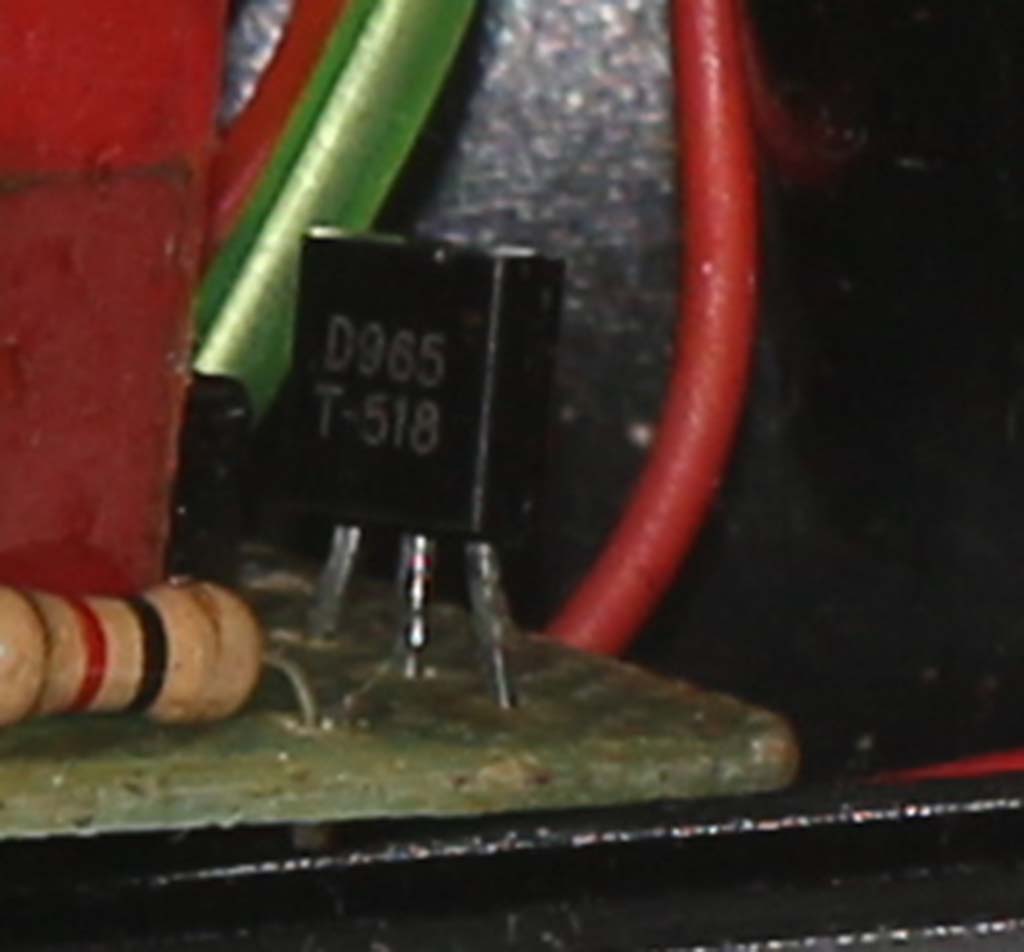
Komponen utama penaik tegangan adalah transistor tipe D965 dan transformator penaik tegangan. Berikut ini foto close-up transistor D965.
Transistor pada raket nyamuk Tecstar
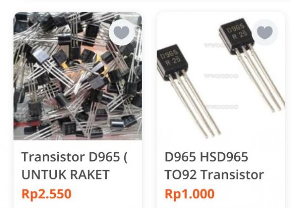
Transistor D965 ini rupanya populer sebagai “transistor raket nyamuk”, seperti di toko online berikut ini:
Transistor D965
Selanjutnya adalah membongkar bagian batere dan charger. Batere menggunakan batere isi ulang tipe NiCD 2.4 volt, 600 mAh.
Raket nyamuk Tecstar: batere dan charger
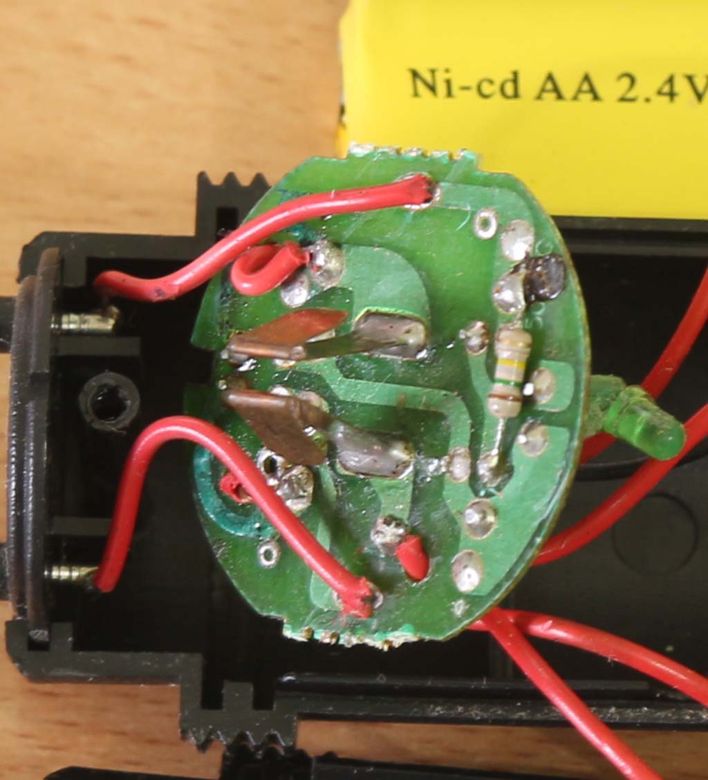
Berikut ini bagian bawah papan rangkaian charger.
Raket nyamuk Tecstar: rangkaian charger bagian bawah
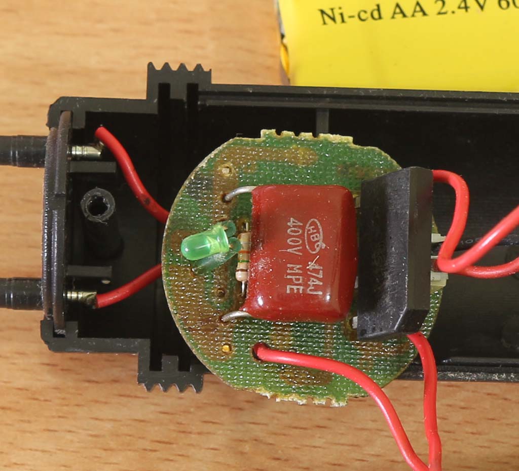
Berikut ini bagian atas charger.
Raket nyamuk Tecstar: rangkaian charger bagian atas
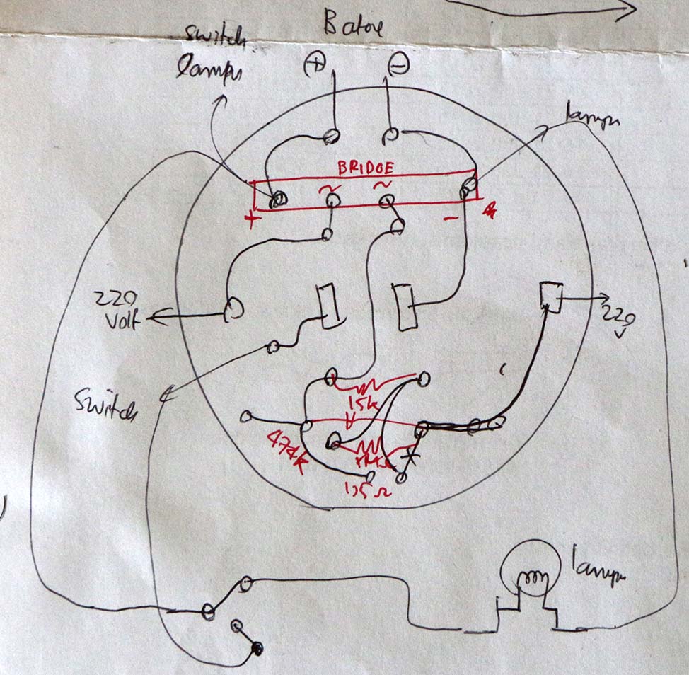
Berikut sketsa skema rangkaian penaik tegangan. Komponen aktif adalah transistor tipe D965.
Rangkaian penaik tegangan di raket nyamuk Tecstar
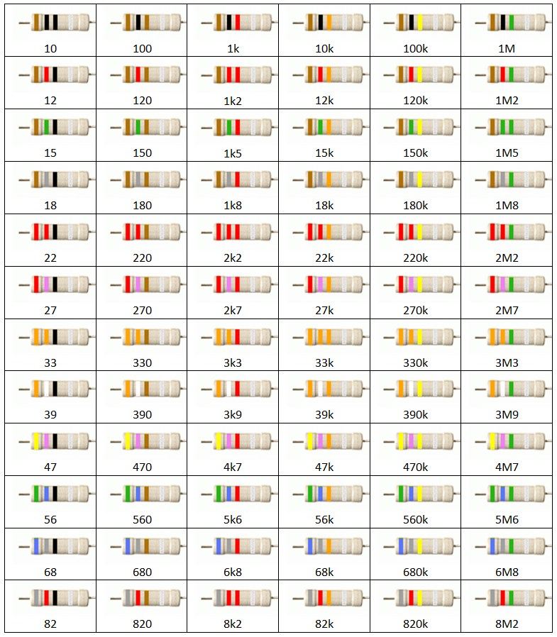
Pada bagian tegangan tinggi ada kapasitor 223J (22 nF), 4 buah dioda tegangan tinggi penyearah (tipe RFC3K) dan 2 buah kapasitor snubber yang tidak jelas nilainya.
Rangkaian dioda dan kapasitor kecil adalah sebagai pelipat tegangan (voltage multiplier). Kapasitor 223J (22 nF) berfungsi sebagai penyimpan tegangan tinggi pada raket. Tegangan inilah yang fungsinya membunuh nyamuk.
Rangkaian charger di raket nyamuk Tecstar
Komponen rangkaian charger hanya sebagai berikut:
Dioda jembatan
Kapasitor 474 (470 nF)
Resistor 15 k
LED indikator
Komponen utama adalah diode bridge dan kapasitor 474 (470 nF). Fungsi dioda bridge adalah penyearah gelombang penuh. Fungsi kapasitor 474 (470 nF) adalah sebagai filter pada penyearah gelombang penuh. Tegangan keluaran penyearah adalah 308 volt (220 x 1,4) sehingga tegangan kerja kapasitor mesti lebih dari 308 volt.
Tidak ada pembatas pengisian, sehingga ketika mengisi kita harus pandai-pandai mengatur kapan pengisian selesai. Kalau terjadi pengisian lebih , ada kemungkinan umur batere berkurang.
Isi ulang raket nyamuk Tecstar
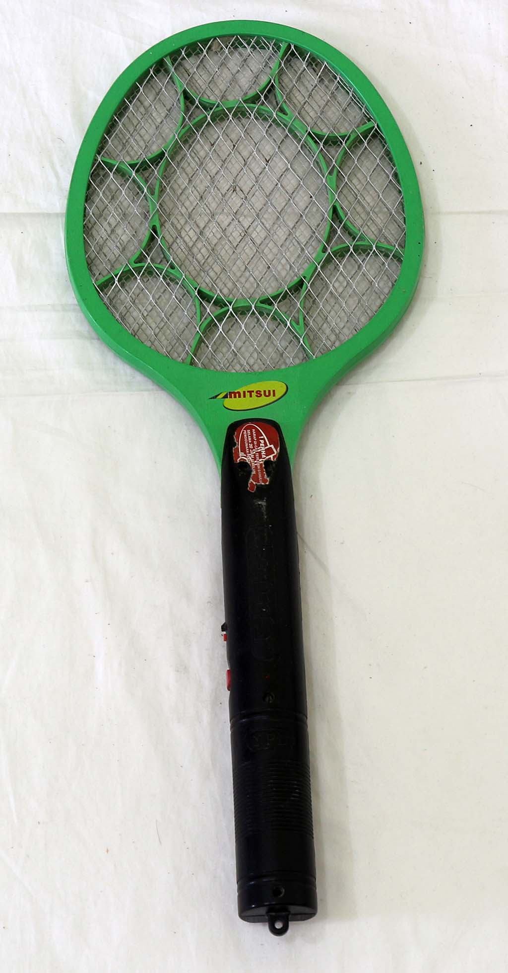
Raket Nyamuk Mitsui
Raket nyamuk Mitsui
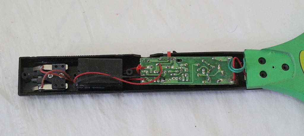
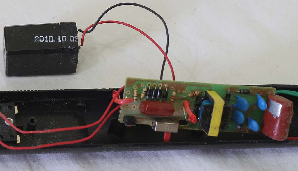
Berikut rangkaian dalam raket nyamuk tersebut.
Raket nyamuk Mitsui
Merek batere yang dipakai tidak jelas, hanya ada angka 2010.10.05 yang kemungkinan adalah tanggal produksi batere.
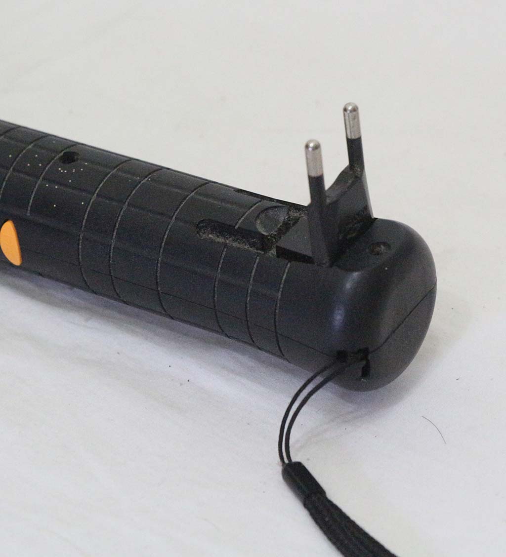
Raket nyamuk ini tidak dapat langsung dicolok ke stop kontak tipe dalam, jadi mesti pakai konverter dulu. Hal ini perlu diperhatikan ketika membeli raket nyamuk, karena harga konverter ini sekitar Rp 10 ribu.
Raket nyamuk Mitsui dengan colokan pendekPengisian batere mesti dengan konverter
Raket Nyamuk Shinyoku
Berikut adalah penampakan raket nyamuk merek Shinyoku.
Raket nyamuk Shinyoku
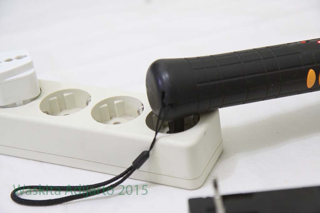
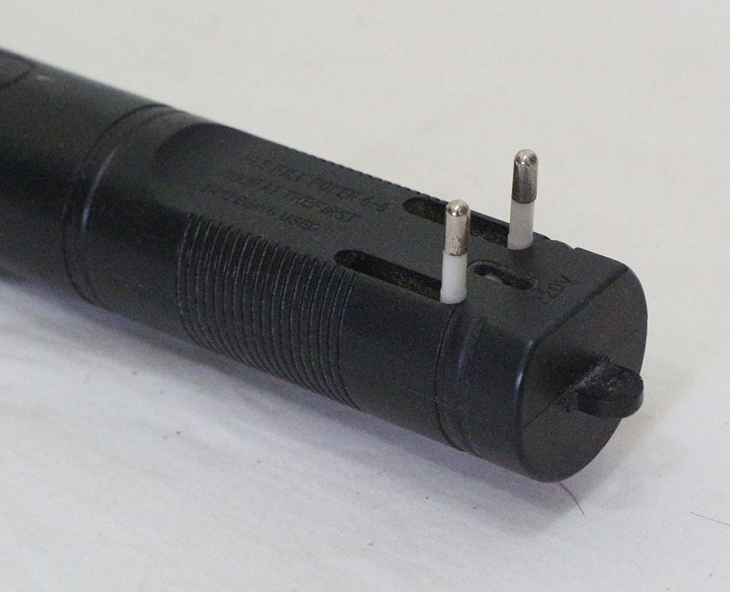
Steker listrik pada raket nyamuk ini cukup panjang, sehingga dapat langsung masuk ke stop kontak yang agak dalam.
Raket nyamuk Shinyoku dengan colokan panjang
Berikut foto raket nyamuk yang sedang di charge dengan stok kontak tipe dalam.
Menyambungkan ke stop kontak dalam
Raket nyamuk ini cukup besar, dan untuk membukanya perlu membuka 7 sekrup.
Raket nyamuk Shinyoku
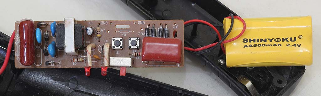
Nampak komponen utama standar: kapasitor tegangan tinggi, transformator tegangan tinggi, transistor, dioda penyearah untuk charger dan batere isi ulang. Tidak disebutkan jenis baterenya, hanya kapasitasnya 500 mAh 2.4 volt.
Raket nyamuk Shinyoku
Berikut bagian bawah papan rangkaian tersebut.
PCB papan rangkaian
Kesimpulan
Dari hasil membongkar 3 raket nyamuk, nampak ada pola kesamaan dan perbedaan.
Persamaan antara lain:
Rangkaian penaik tegangan menggunakan osilator dengan 1 transistor dan 1 transformator.
Batere menggunakan batere isi ulang.
Rangkaian charger batere sangat sederhana, hanya menggunakan penyearah jembatan (bridge rectifier) dengan 4 dioda, dan kapasitor serta resistor untuk pembatas arus. Artinya tidak ada pembatasan pengisian batere, sehingga sangat mungkin terjadi over-charge atau pengisian batere berlebih yang dapat merusak batere.
Tegangan AC dari transformator tegangan tinggi disearahkan dengan dioda tegangan tinggi. Pada Tecstar menggunakan dioda tipe RFC3K, sedangkan pada raket lain tidak jelas jenis dioda yang dipakai.
Perbedaan
Batere pada model Tecstar menyatakan menggunakan NiCd, sedangkan Shinyuoku dan Mitsui tidak jelas.
Colokan listrik ada yang panjang, ada yang pendek.
Ada raket yang dilengkapi dengan lampu, ada yang tidak.
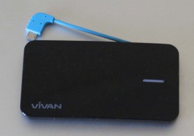
Powerbank Vivan M04 adalah sebuah powerbank dengan kapasitas 3500 mAh. Berikut ini beberapa foto penampakan powerbank ini.
Penampakan
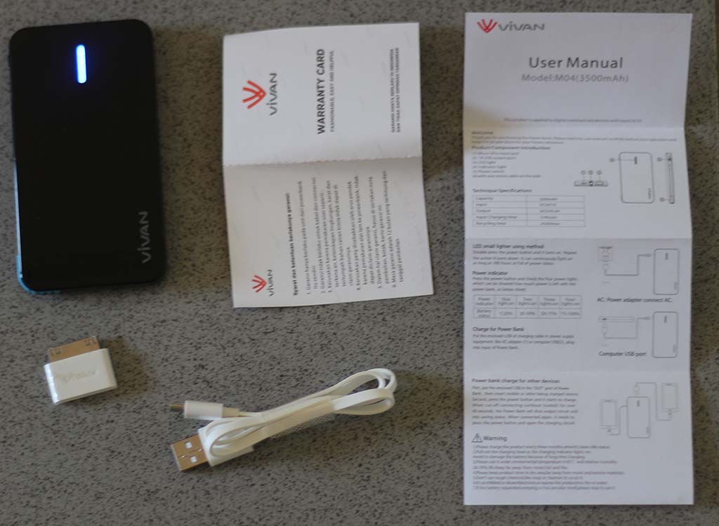
Powerbank Vivan M04: isi paket
Isi paket pembeliannya yang saya dapatkan adalah powerbank, manual, kartu garansi, kabel charger USB micro dan konverter USB
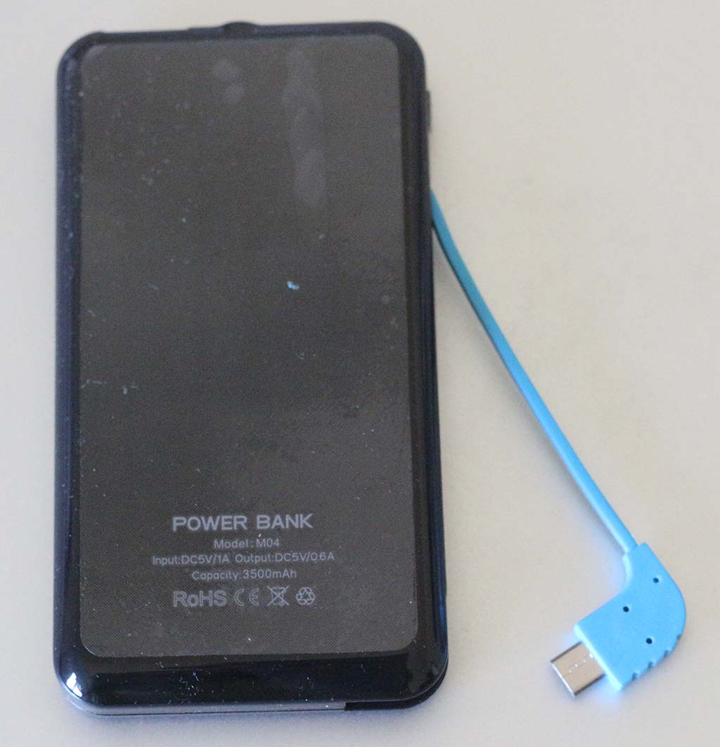
Powerbank Vivan M04 penampakan dari belakang
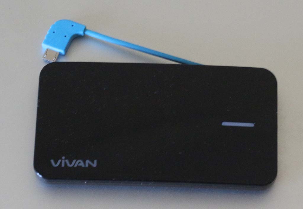
Berikut ini adalah penampakan bagian depan powerbank Vivan M04
Powerbank Vivan M04: penampakan depan
Manual Bahasa Inggris
Manual Vivan M04 tersedia dalam 2 bahasa: Inggris dan Indonesia. Di dalam manualnya terdapat beberapa salah ketik dan istilah, namun secara umumu isinya cukup dapat dipahami.
Manual Vivan M04 bahasa Inggris
Berikut teks manual dalam bahasa Inggris
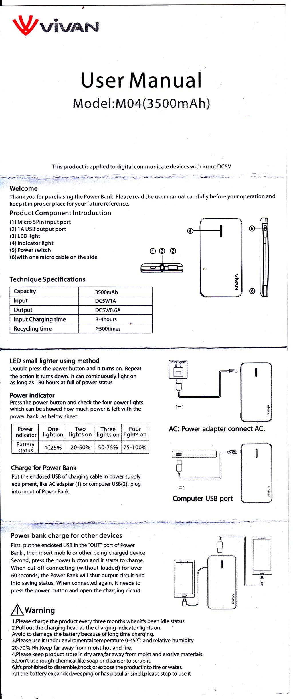
User Manual
Model:M04(3500mAh)
This product is applied to digital communicate devices with input DC5V
Welcome
Thankyou for purchasing the Power Bank. Please read the user manual carefully before your operation and keep it in proper place for your future reference.
Product Component Introduction
Micro SPin input port
1A USB output port
LED light
indicator light
Power switch
with one micro cable on the side
Technique Specifications
Capacity
3500m Ah
Input
DC5V/1A
Output
DC5V/0.6A
Input Charging time
3-4hours
Recycling time
>=500times
LED small lighter using method
Double press the power button and it turns on. Repeat the action it turns down. It can continuously light on as long as 180 hours at full of power status
Power indicator
Press the power button and check the four power lights which can be showed how much power is left with the power bank, as below sheet:
Power Indicator
one light on
two lights on
three lights on
four lights on
Battery Status
<=25%
20-50%
50-75%
75-100%
Charge for Power Bank
Put the enclosed USB of charging cable in power supply equipment, like AC adapter (1) or computer USB(2), plug into input of Power Bank.
Power bank charge for other devices
First, put the enclosed USB in the “OUT port of Power Bank, then insert mobile or other being charged device. Second, press the power button and it starts to charge. When cut off connecting (without loaded) for over 60 seconds, the Power Bank will shut output circuit and into saving status. When connected again, it needs to press the power button and open the charging circuit.
Warning
Please charge the product every three months when it’s been idle status.
Pull out the charging head as the charging indicator lights on. Avoid to damage the battery because of long time charging.
Please use it under enviromental temperature 0-45 *C and relative humidity 20-70% Rh.Keep far away from moist,hot and fire.
Please keep product store in dry area,far away from moist and erosive materials.
Don’t use rough chemical,like soap or cleanser to scrub it
t’s prohibited to dissemble,knock,or expose the product into fire or water.
If the battery expanded,weeping or has peculiar smell,please stop to use it
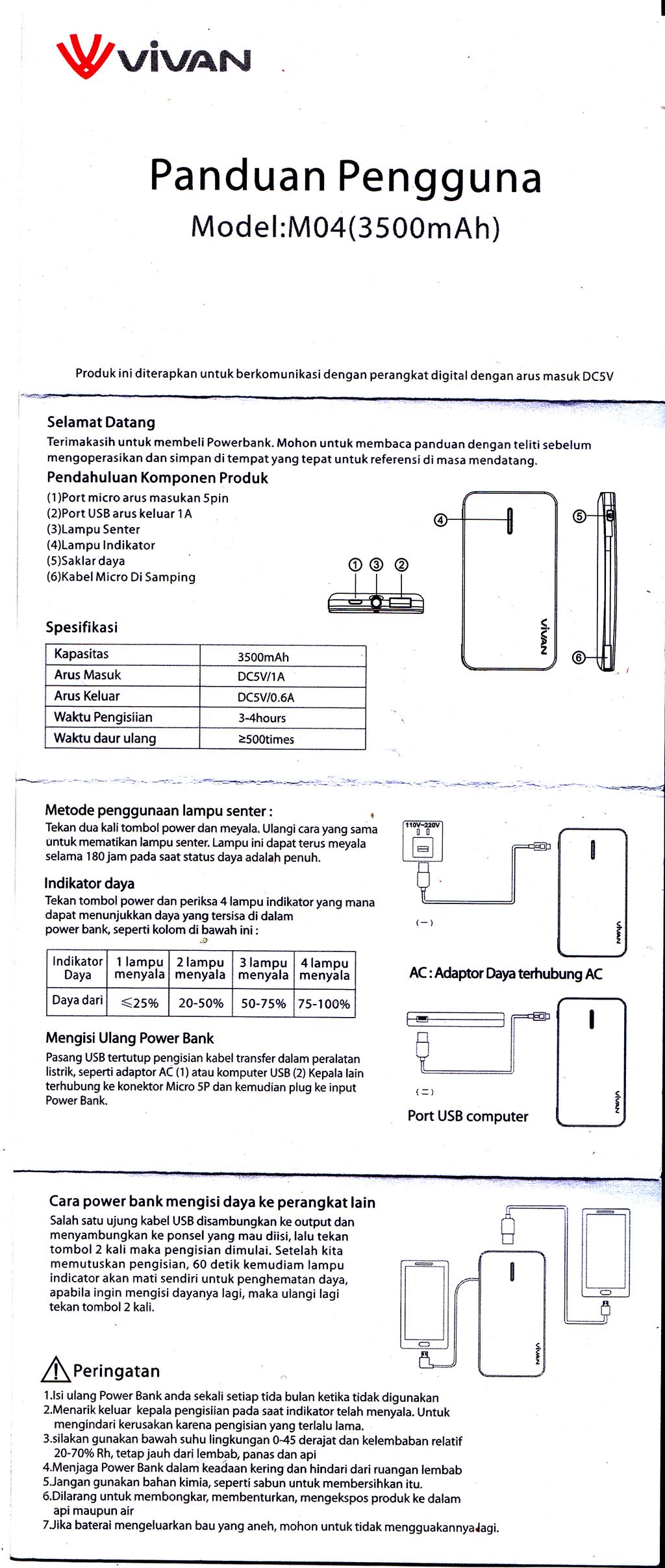
Manual Bahasa Indonesia
Manual Vivan M04 bahasa Indonesia
Berikut teks manual dalam bahasa Indonesia
VIVAN
Panduan Pengguna
Model:M04(3500mAh)
Produk ini diterapkan untuk berkomunikasi dengan perangkat digital dengan arus masuk DC5V
Selamat Datang
Terimakasih untuk membeli Powerbank. Mohon untuk membaca panduan dengan teliti sebelum mengoperasikan dan simpan di tempat yang tepat untuk referensi di masa mendatang.
Pendahuluan Komponen Produk
(1 )Port micro arus masukan 5pin
(2) Port USBaruskeluar 1A
(3) Lampu Senter
(4) Lampu Indikator
(5) Saklar daya
(6) Kabel Micro Di Samping
Spesifikasi
Kapasitas 3500mAh
Arus Masuk DC5V/1A
Arus Keluar DC5V/0.6A
Waktu Pengisiian 3-4hours
Waktu daur ulang £500times
®ifl
Metode penggunaan lampu senter: •
Tekan dua kali tombol power dan meyala. Ulangi cara yang sama untuk mematikan lampu senter. Lampu ini dapatterus meyala selama 180 jam pada saat status daya adalah penuh.
Indikator daya
Tekan tombol power dan periksa 4 lampu indikator yang mana dapat menunjukkan daya yang tersisa di dalam power bank, seperti kolom di bawah ini: j>
Indikator Daya 1 lampu menyala 2 lampu menyala 3 lampu menyala 4 lampu menyala
Daya dari *S25% 20-50% 50-75% 75-100%
AC: Adaptor Daya terhubung AC
Mengisi Ulang Power Bank
Pasang USB tertutup pengisian kabel transfer dalam peralatan listrik, seperti adaptor AC (1) atau komputer USB (2) Kepala lain terhubung ke konektor Micro SP dan kemudian plug ke input Power Bank.
Port USB computer
Cara power bank mengisi daya ke perangkat lain Salah satu ujung kabel USB disambungkan ke output dan menyambungkan ke ponsel yang mau diisi, lalu tekan tombol 2 kali maka pengisian dimulai. Setelah kita memutuskan pengisian, 60 detik kemudiam lampu indicator akan mati sendiri untuk penghematan daya, apabila ingin mengisi dayanya lagi, maka ulangi lagi tekan tombol 2 kali.
/f\Peringatan
Isi ulang Power Bank anda sekali setiaptida bulan ketika tidakdigunakan
Menarik keluar kepala pengisiian pada saat indikator telah menyala. Untuk mengindari kerusakan karena pengisian yang terlalu lama.
Silakan gunakan bawah suhu lingkungan 0-45 derajat dan kelembaban relatif 20-70% Rh, tetap jauh dari lembab, panas dan api
Menjaga Power Bank dalam keadaan kering dan hindari dari ruangan lembab
Jangan gunakan bahan kimia, seperti sabun untuk membersihkan itu.
Dilarang untuk membongkar, membenturkan, mengekspos produk ke dalam api maupun air
Jika baterai mengeluarkan bau yang aneh, mohon untuk tidak mengguakannya lagi.
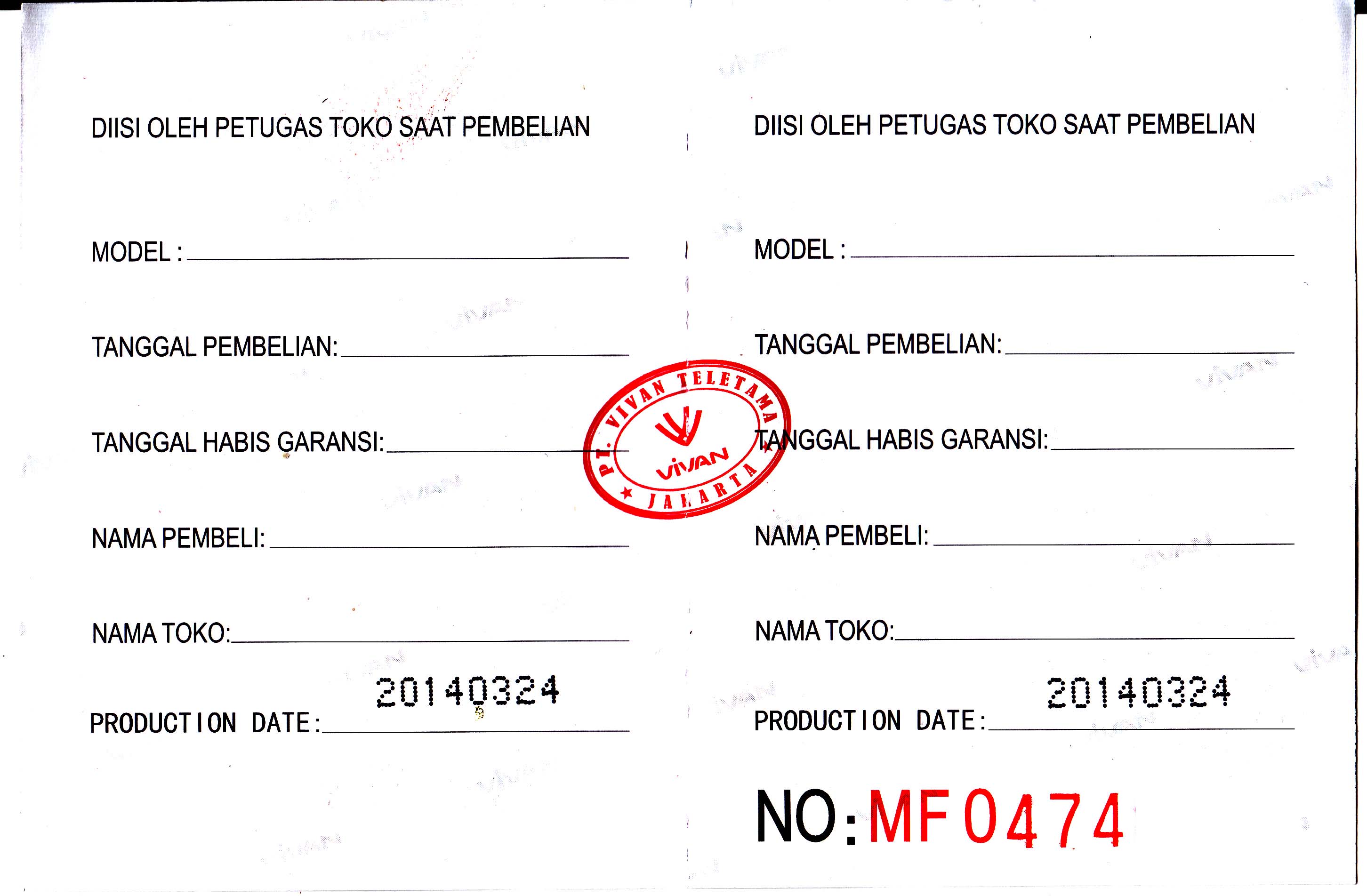
Kartu Garansi
Berikut adalah scan kartu garansi Vivan M04. Di situ tercantum syarat dan ketentuan berlakunya garansi.
Kartu garansi Vivan M04Kartu garansi Vivan M04
Syarat dan ketentuan berlakunya garansi:
Garansi hanya berlaku pada unit dari powerbank itu sendiri
Garansi tidak berlaku untuk kabel dan connector
Kerusakan karena pemakaian user seperti: terkena air, kelembapan lingkungan, karat dan tertumpah bahan cairan kimia tidak dapat di claim garansinya.
Kerusakan yang disebabkan oleh arus pendek karena pemakaian alat lain ke powerbank, tidak dapSt diclaim garansinya
Dalam hal claim garansi, harus di sertakan nota pembelian, kotak, kartu garansi ini
Masa garansi adalah 12 bulan yang terhitung dari tanggal pembelian
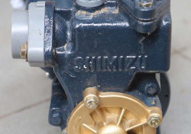
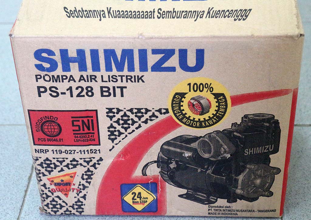
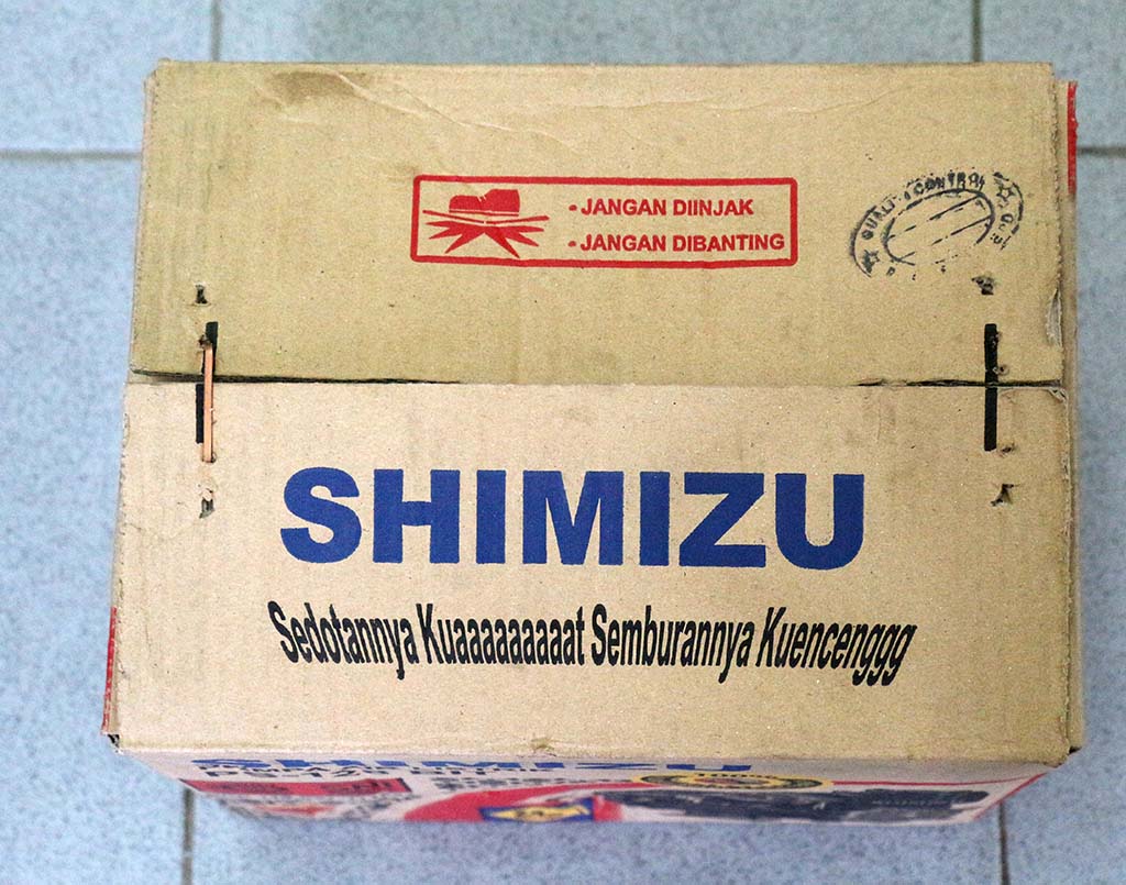
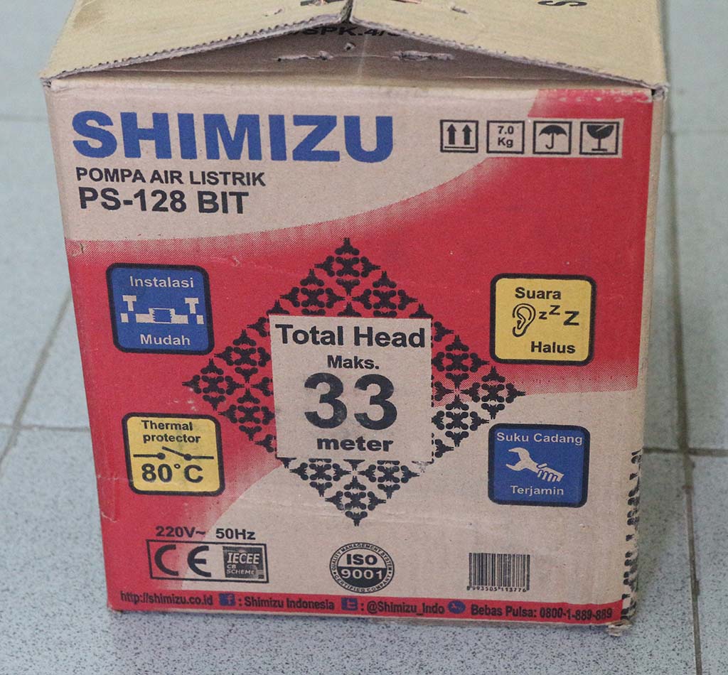
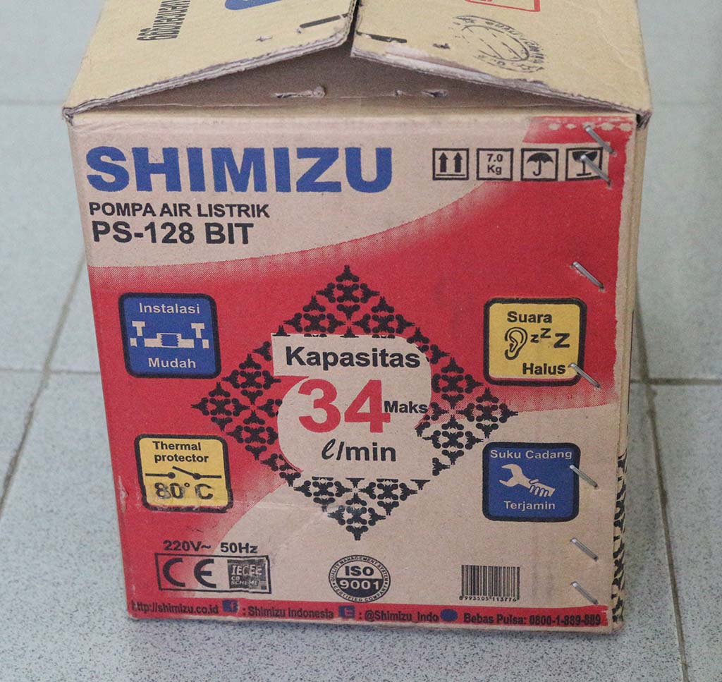
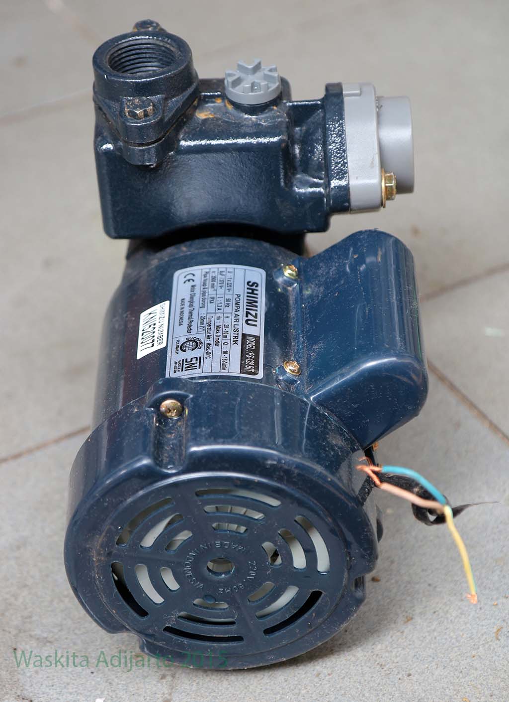
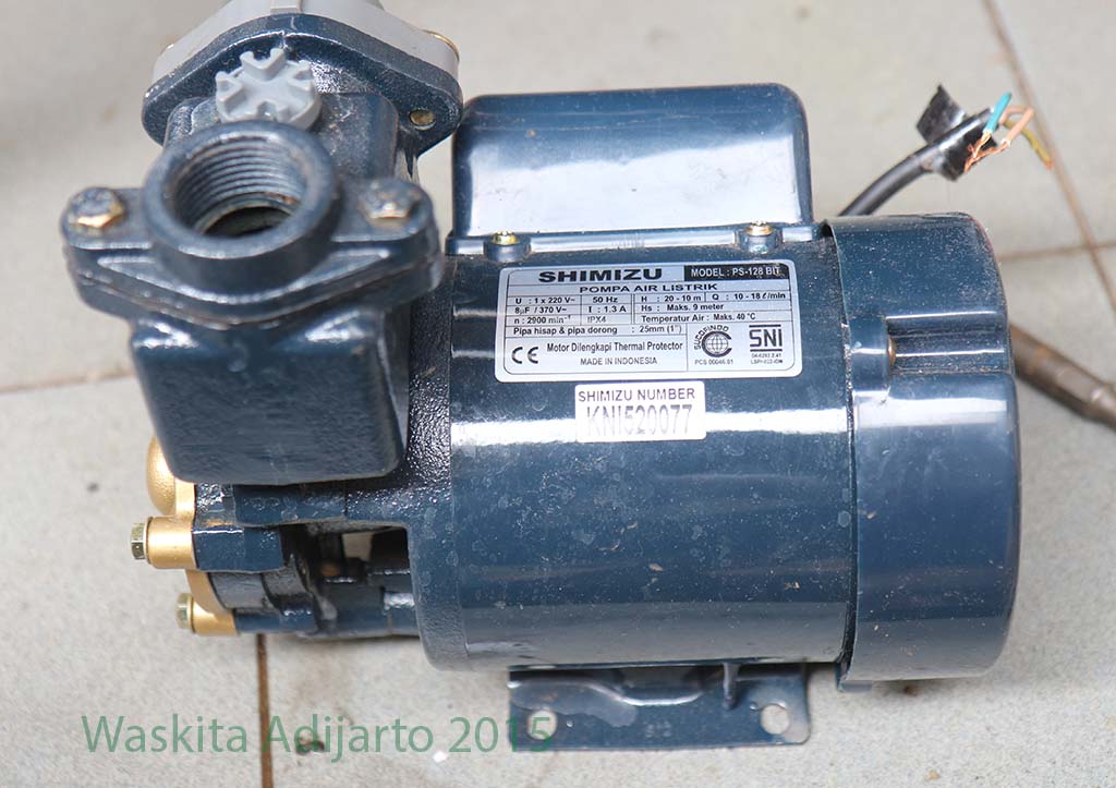
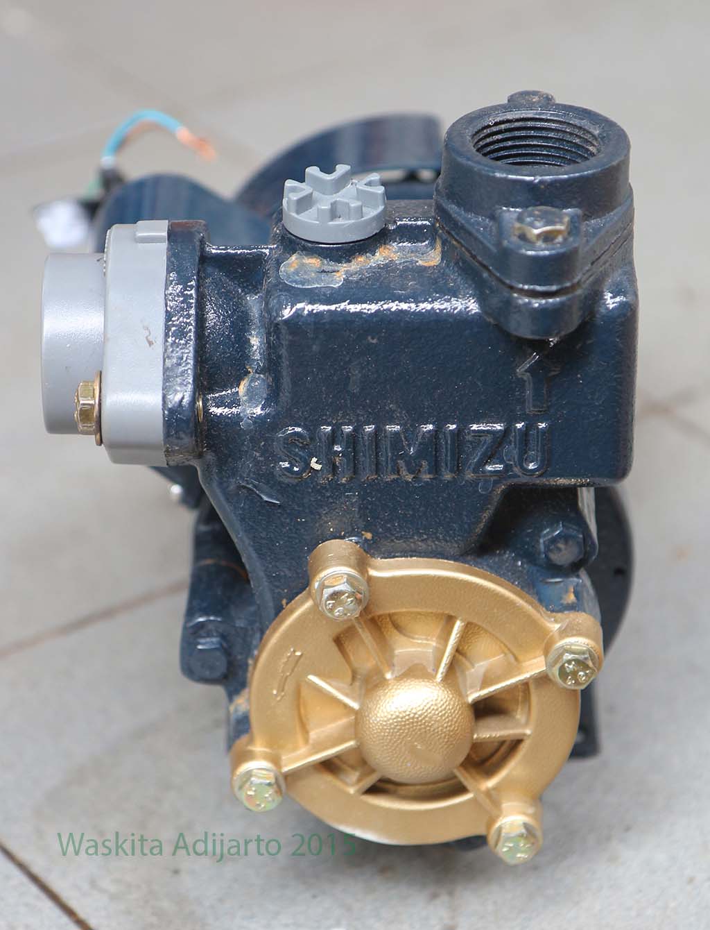
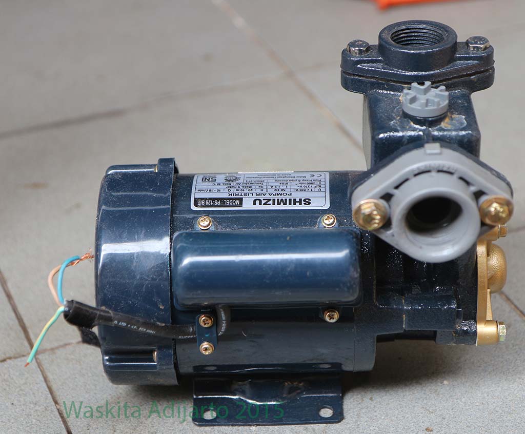
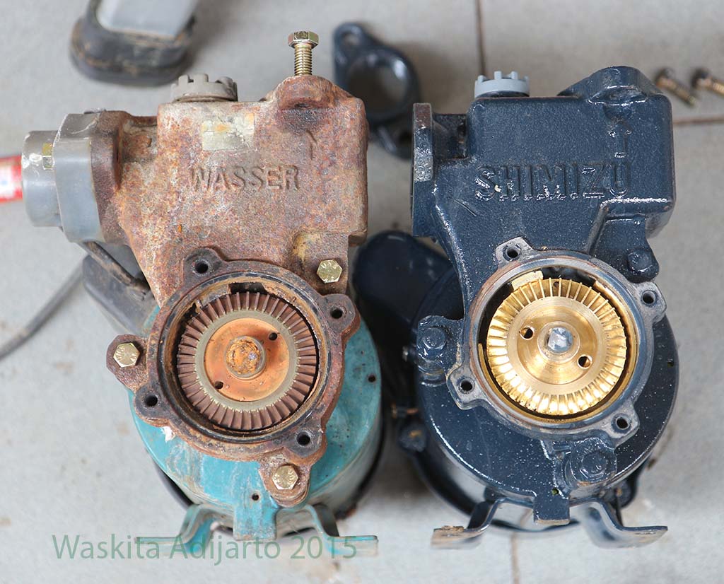
Pompa air Shimizu PS 128 BITPompa air Shimizu PS 128 BIT: penampakan sampingPompa air Shimizu PS 128 BIT : bagian impeller. Penutup kuning kesannya dari bahan kuningan, tapi ternyata bahannya adalah plastik. yang di dalamnya ada kuninganPompa air Shimizu PS 128 BIT: penampilan samping.
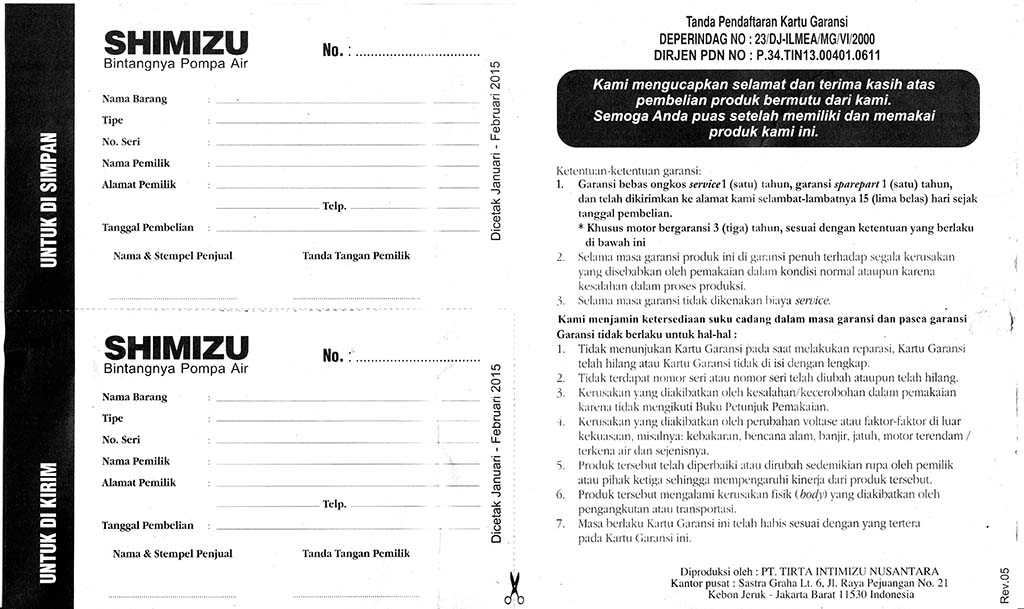
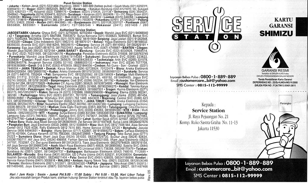
Kartu Garansi
Pompa Shimizu ini digaransi selama 1 tahun atas kerusakan akibat pemakaian normal maupun kesalahan proses produksi.
Kartu garansiKartu garansi
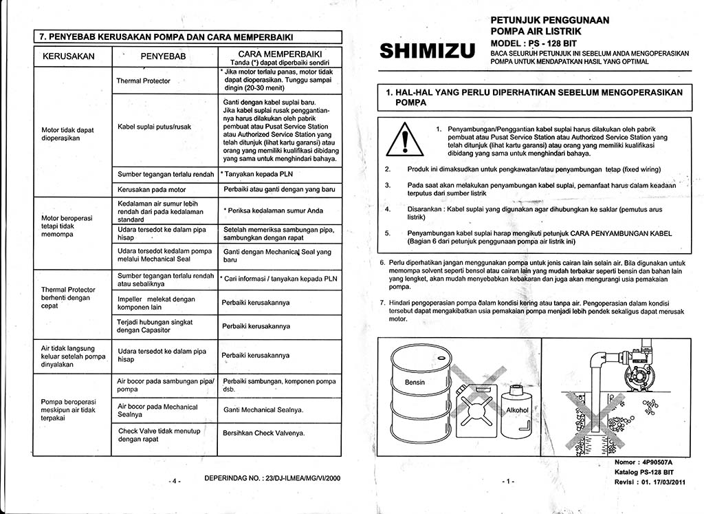
Manual
Berikut ini hasil scan manual pompa air Shimizu PS-128 BIT:
Manual Shimizu PS-128 BIT halaman 1 dan 4Manual Shimizu PS-128 BIT halaman 2 dan 3
Manual Hasil OCR
Berikut manual yang telah di OCR
PETUNJUK PENGGUNAAN POMPA AIR LISTRIK MODEL: PS-128 BIT
BACA SELURUH PETUNJUK INI SEBELUM ANDA MENGOPERASIKAN POMPA UNTUK MENDAPATKAN HASH YANG OPTIMAL
SHIMIZU
1. HAL-HAL YANG PERLU DIPERHATIKAN SEBELUM MENGOPERASIKAN POMPA
1. Penyambungan/Penggantian kabel suplai harus dilakukan oleh pabrik pembuat atau Pusat Service Station atau Authorized Service Station yang telah ditunjuk (lihat kartu garansi) atau orang yang memiliki kualifikasi di bidang yang sama untuk menghindari bahaya.
2. Produk ini dimaksudkan untuk pengkawatan/atau penyambungan tetap (fixed wiring)
3. Pada saat akan melakukan penyambungan kabel suplai, pemanfaat harus dalam keadaan terputus dari sumber listrik
4. Disarankan : Kabel suplai yang digunakan agar dihubungkan ke saklar (pemutus arus listrik)
5. Penyambungan kabel suplai harap mengikuti petunjuk CARA PENYAMBUNGAN KABEL (Bagian 6 dari petunjuk penggunaan pompa air listrik ini)
6. Perlu diperhatikan jangan menggunakan pompa untuk jenis cairan lain selain air. Bila digunakan untuk memompa solvent seperti bensol atau cairan l|Sn yang mudah terbakar seperti bensin dan bahan lain yang lengket, akan mudah menyebabkan kebikaran dan juga akan mengurangi usia pemakaian pompa.
7. Hindari pengoperasian pompa dalam kondisi kering atau tanpa air. Pengoperasian dalam kondisi tersebut dapat mengakibatkan usia pemakaian {pompa menjadi lebih pendek sekaligus dapat merusak motor.
8. Jangan membungkus motor atau pompa dengan kain atau selimut. Karena hal ini dapat menyebabkan kebakaran.
9. Hindari pengoperasian pompa dalam kondisi suhu iebih dari 40°C dan di bawah -10°C danjuga pada suhu air Iebih dari 40°C, karena hat ini akan memperpendek usia pemakaian pompa.
10. Hindarkan pompa dari kondisi di bawah sinar matahari langsung atau hujan (Gb.1), karena ini akan menyebabkan usia pompa menjadi Iebih pendek dan juga bahaya kejutan listrik.
11. Bila pompa selesai dipasang pada sumur yang mudah menghisap kotoran terutama pasir maka diperlukan adanya saringan pasir (Gb 2). Hal ini untuk mencegah impeller pada pompa cepat aus (rusak) dalam waktu yang singkat , penurunan tekanan yang mengakibatkan berkurangnya air yang dipompa.
12. Tegangan listrik yang diizinkan untuk pompa ini adalah ±10% dari tegangan terpasang. Diluar ketentuan ini dapat memperpendek usia pompa.
BILA POMPA DIGUNAKAN KEMBALISETELAH TIDAK DIPAKAI DALAM WAKTU YANG LAMA
Ada kemungkinan motor tidak dapat dioperasikan, karena mengerasnya debu dan kotoran dari air pada pump head, langkah yang dilakukan : matikan sumber arus, lalu putar as motor (shaft) beberapa kali dengan obeng atau benda sejenisnya (Gb.3). Setelah itu anda dapat mengoperasikan pompa seperti biasa.
2. BENTUK DAN NAMA-NAMA KOMPONEN POMPA
3. Cara Mengoperasikan Pompa
1. Pompa ini membutuhkan sedikit air pancingan pada saat pertama kali dioperasikan.
2. Pancinglah, buka penutup lubang pancingan pada pompa (Plug) tuangkan air pancingan hingga rumah pompa terisi penuh oleh air.
3. Pasang kembali penutup lubang pancingan (Plug) dan tutup semua kran.
4. Hidupkan pompa air listrik, selanjutnya tunggu beberapa saat sampai pompa menghisap air, kemudian buka kran secukupnya, dan air akan keluar.
5. Jika air tidak keluar, mungkin disebabkan oleh kurangnya air pancingan, jadi ulangilah tahap pancingan tersebut.
Penyebab Kerusakan Pompa Dan Cara Memperbaikinya
Kerusakan
Penyebab
Cara Memperbaiki
Motor tidak dapat dioperasikan
Thermal Protector
Jika motor terlalu panas, motor tidak dapat dioperasikan. Tunggu sampai dingin (20-30 menit)
Kabel suplai putus/rusak
Jika kabel suplai rusak penggantian-nya harus dilakukan oleh pabrik pembuat atau Pusat Service Station atau Authorized Service Station yang telah ditunjuk (lihat kartu garansi) atau orang yang memiliki kualifikasi dibidang yang sama untuk menghindari bahaya.
Sumber tegangan terlalu rendah
Tanyakan kepada PLN
Kerusakan pada motor
Perbaiki atau ganti dengan yang baru
Motor beroperasi tetapi tidak memompa
Kedalaman air sumur lebih rendah dari pada kedalaman standard
Periksa kedalaman sumur Anda
Udara tersedot ke dalam pipa hisap
Setelah memeriksa sambungan pipa, sambungkan dengan rapat
Udara tersedot kedalam pompa melalui Mechanical Seal
Ganti dengan Mechanical Seal yang baru
Thermal Protector berhenti dengan cepat
Sumber tegangan terlalu rendah atau sebaliknya
* Cari informasi / tanyakan kepada PLN
Impeller melekat dengan komponen lain
Perbaiki kerusakannya
Terjadi hubungan singkat dengan Capasitor
Perbaiki kerusakannya
Air tidak langsung keluar setelah pompa dinyalakan
Udara tersedot ke dalam pipa hisap
Perbaiki kerusakannya
Pompa beroperasi meskipun air tidak terpakai
Air bocor pada sambungan pipa/ pompa
Perbaiki sambungan, komponen pompa dsb.
Air bocor pada Mechanical Sealnya
Ganti Mechanical Sealnya.
Check Valve tidak menutup dengan rapat
Bersihkan Check Valvenya.
Pompa Air Kembar
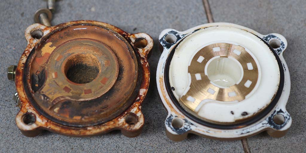
Pompa air Shimizu PS-128BIT ini ternyata mirip sekali dengan Wasser PW-131E. Berikut ini beberapa foto penampakannya. Bagian penutup impeller bentuknya mirip dan menggunakan teknik material yang sama, yaitu bahan dasar plastik dengan kuningan untuk bagian yang menempel dengan impeller.
Penutup impeller Wasser dan Shimizu
Bagian impeller juga bentuknya serupa. Hampir tidak ada perbedaan kalau dilihat dari sudut pandang ini.
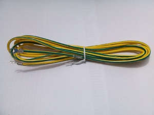
Untuk amannya, pompa air perlu disambung ke pentanahan yang baik. Kabel yang biasa dipakai adalah kabel warna kuning-hijau, dengan ukuran yang mampu dialiri arus yang sesuai dengan MCB di rumah. Lihat saja kabel ground/ardee yang terpasang di panel listrik anda, kalau instalasinya betul ukurannya sudah standar, sesuai dengan kapasitas listrik yang terpasang di rumah.
Diagram alir (flow chart) adalah salah satu teknik untuk memodelkan perangkat lunak. Pada tulisan ini diuraikan secara ringkas diagram alir pada perangkat lunak desktop, mikroprosesor dengan superloop, mikroprosesor dengan interupsi dan mikroprosesor dengan multitasking.
Diagram alir adalah sebuah diagram dengan simbol-simbol grafis yang menyatakan aliran algoritma atau proses yang menampilkan langkah-langkah yang disimbolkan dalam bentuk kotak, beserta urutannya dengan menghubungkan masing masing langkah tersebut menggunakan tanda panah. Diagram ini bisa memberi solusi selangkah demi selangkah untuk penyelesaian masalah yang ada di dalam proses atau algoritma tersebut
Secara umum diagram alir dipakai untuk melakukan analisis, perancangan, dokumentasi, ataupun manajemen suatu proses atau program dalam berbagai bidang ilmu.
Dalam tulisan ini disajikan penggunaan diagram alir untuk melihat perbedaan antara 3 macam perangkat lunak:
Perangkat lunak desktop
Perangkat lunak sistem mikroprosesor tanpa sistem operasi
Perangkat lunak sistem mikroprosesor dengan sistem operasi
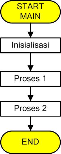
Diagram Alir Perangkat Lunak Desktop
Perangkat lunak desktop yang dibahas di sini maksudnya adalah perangkat lunak yang dijalankan pada suatu sistem operasi (misal Windows / Linux). Perangkat lunak seperti ini dijalankan pada suatu saat dan kemudian selesai pada beberapa waktu kemudian. Jadi pada perangkat lunak ini ada bagian START sebagai permulaan dan ada bagian END yang menyatakan akhir pelaksanaan perangkat lunak tersebut.
Diagram alir perangkat lunak desktop
Pada contoh di atas, program melaksanakan 3 buah pekerjaan yaitu Inisialisasi, Proses 1 dan Proses 2, kemudian berhenti. Pekerjaan dapat bermacam-macam, namun intinya adalah ada START di awal dan END di akhirnya.
Contoh perangkat lunak seperti ini misalnya adalah web browser yang anda pakai sekarang (Firefox,Chrome, Internet Explorer, Safari, dsb). Contoh lainnya adalah perangkat lunak command line di Windows maupun Linux.
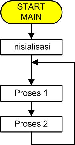
Diagram Alir Perangkat Lunak Berbasis Super Loop Tanpa Interupsi
Model berikutnya adalah model perangkat lunak yang umum dipakai pada sistem mikroprosesor/mikrokontroler. Pada sistem mikroprosesor perangkat lunak diharapkan untuk berjalan selamanya sampai perangkat tersebut dimatikan atau direset. Ciri diagram alir pada sistem ini adalah ada bagian START namun tidak END, dan ada suatu loop yang dijalankan selamanya. Karena ada loop yang dijalankan selamanya ini, maka arsitektur seperti ini sering disebut sebagai superloop.
Bagian utama software ada 2 yaitu bagian inisialisasi dan proses/pekerjaan. Bagian inisialisasi hanya dilakukan satu kali saja di awal, umumnya untuk melakukan konfigurasi pada sistem mikroprosesor yang digunakan. Contohnya adalah mengaktifkan port-port tertentu sebagai input maupun output, mengatur port serial, mengatur timer/pewaktu, dan lain-lain perangkat di dalam mikroprosesor/mikrokontroler tersebut.
Diagram alir superloop tanpa interupsi
Teknik pembuatan superloop dalam bahasa C umumnya menggunakan loop while(1) {} ataupun for(;;){}.
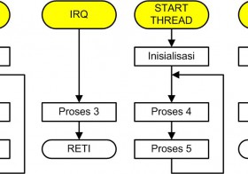
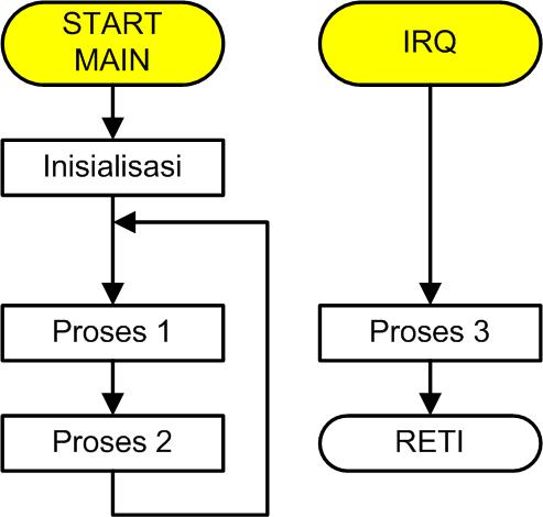
Diagram Alir Perangkat Lunak Berbasis Super Loop Dengan Interupsi
Model ini adalah perkembangan dari model sebelumnya. Perbedaannya adalah pada perangkat lunak ini ada fungsi / subroutine yang bertugas menangani adanya interupsi. Software untuk menangani interupsi ini sering disebut juga sebagai Interrupt Service Routine (ISR).
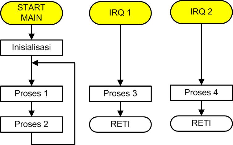
ISR ini berjalan seolah-olah tidak tergantung pada diagram alir utama, sehingga untuk memodelkan perangkat lunak ISR kita mesti membuat sebuah diagram alir terpisah. ISR dimulai dari adanya sebuah IRQ (Interrupt Request) yaitu sinyal dari hardware yang menandakan adanya suatu interupsi yang mesti dilayani. Setelah IRQ tersebut, maka ISR melaksanakan proses yang diperlukan untuk melayani IRQ tersebut sampai selesai. Setelah selesai maka ISR akan menjalankan RETI (Return from Interrupt) untuk mengakhiri ISR.
Diagram alir superloop dengan interupsi
Suatu perangkat lunak dapat memiliki beberapa ISR, sehingga untuk masing-masing ISR ini mesti dibuatkan flowchart sendiri. Pada contoh berikut ini ada 2 buah interupsi, yaitu IRQ 1 yang menjalankan Proses 3, dan IRQ 2 yang menjalankan Proses 4.
Diagram alir superloop dengan 2 interupsi
Diagram Alir Perangkat Lunak Dengan Multithread
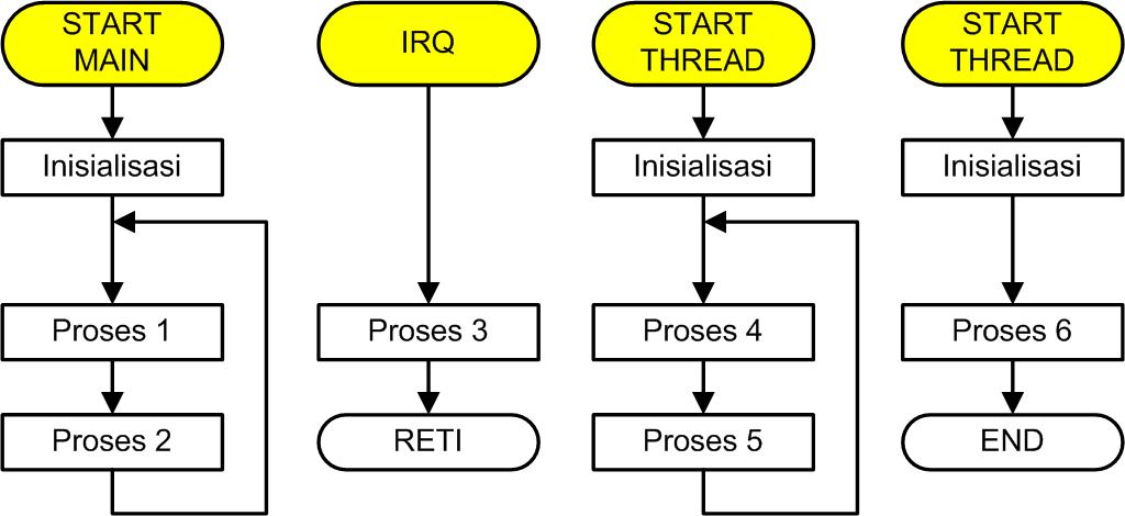
Berikutnya yang paling kompleks adalah diagram alir perangkat lunak dengan sistem operasi multithread. Pada perangkat lunak ini terdapat superloop dan interupsi seperti sebelumnya, namun ada lagi 1 fitur software yang tidak ada di software sebelumnya, yaitu multithreading. Pada multithreading, sistem mikroprosesor dapat menjalankan beberapa thread software sekaligus walaupun hanya memiliki 1 CPU saja. Tekniknya adalah dengan membagi waktu CPU antara beberapa thread yang aktif, sehingga meskipun hanya ada 1 CPU namun seolah-olah komputer ini memiliki beberapa CPU yang masing-masing menjalankan program tersendiri.
Perbedaan utamanya adalah pada multithread kita dapat membuat beberapa superloop, 1 di main loop, sedangkan loop lain dapat diaktifkan sebagai thread.
Diagram alir perangkat lunak dengan sistem operasi
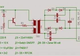
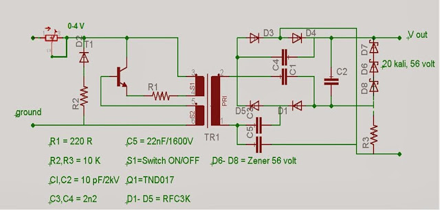
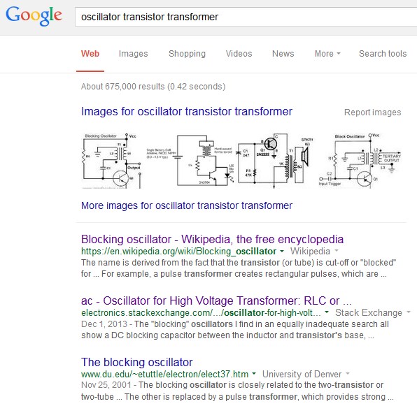
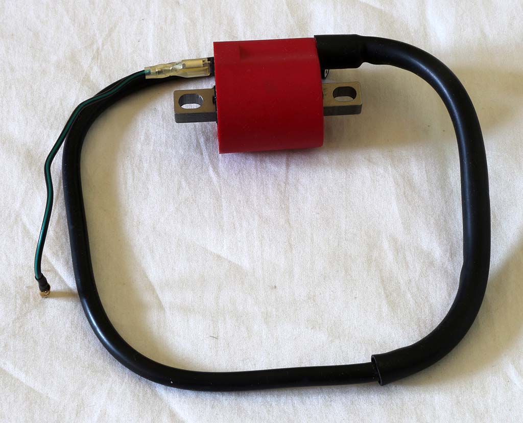
Di beberapa situs lain rangkaian ini banyak di-copy paste, entah sumber asalnya dari mana. Rangkaian ini nampaknya sederhana, tidak terlalu banyak komponennya. Komponen aktif hanya sebuah transistor. Pembangkitan tegangan tinggi dengan trafo memerlukan sinyal AC, padahal inputnya batere DC, jadi kesimpulannya mesti ada pembangkit sinyal AC pada rangkaian tersebut.
Komponen utama rangkaian ini adalah sebuah transistor dan sebuah trafo / transformator. Dari data-data tersebut, bisa dicoba untuk mencari nama rangkaian ini, dapat kita gunakan kata kunci ‘transistor’, ‘transformer’, ‘oscillator’.
Pencarian oscillator transistor transformer
Dari hasil googling dan melihat artikel di wikipedia tersebut, nampaknya rangkaian yang dipakai adalah ‘Blocking Oscillator‘ atau ‘Osilator Sumbatan‘, dengan modifikasi berupa memasang kumparan sekunder di trafo yang dipakai tersebut. Hebat juga orang Indonesia editor wikipedia, karena artikel ‘Blocking Oscillator’ tersebut hanya ada dalam 5 bahasa: English, Indonesia, Deutsch (Jerman) , Русский (Rusia) dan Українська (Ukraina).
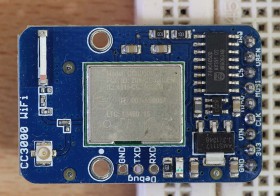
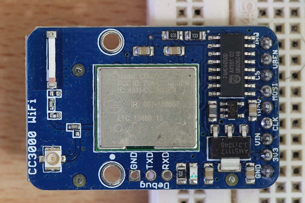
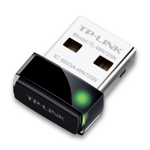
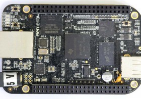
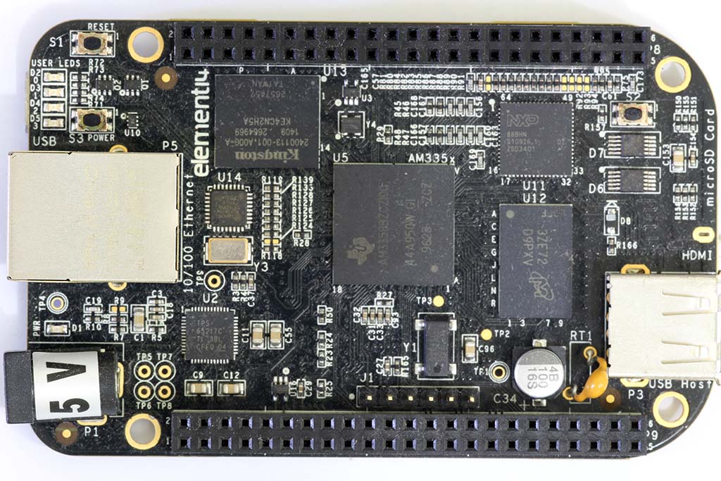
Driver untuk Wireless TP-Link WN725N belum tersedia pada OS yang diinstall pada Beaglebone Black, jadi kalau kita mau menggunakan WN724N kita mesti compile sendiri driver tersebut. Berikut ini beberapa prosedur yang berhasil dikumpulkan.
sudo pico interfacesThen uncomment or add in the following text:
# wireless network interface
auto wlan0
iface wlan0 inet dhcp
wpa-ssid “Wifi Network Name”
wpa-psk “wifipassword”
sudo reboot
The green light should now be blinking! You should be able to ping it. Check your router status to find the IP address. If you’re plugged in with an ethernet cable, keep reading. Else skip to step 33!
If you have an ethernet cable, unplug it. You will now no longer be able to ping/connect to the wireless IP address of the beaglebone black.
Remove the power from the beaglebone black.
Hold the reset button and plug the power back in and let it boot up.
You should now be able to ping/connect to the beaglebone black wirelessly. Congrats!
Edit network interface setting: nano /etc/network/interfaces
Add or uncomment the following lines:
Then uncomment or add in the following text in the file:
# wireless network interface
auto wlan0
iface wlan0 inet dhcp
wpa-ssid “Wifi Network Name”
wpa-psk “wifipassword”
reboot
If everything is right, output of ‘ifconfig -a’ should be like this:
cd /usr/src/kernel
make scripts
ln -s /usr/src/kernel /lib/modules/$(uname -r)/build
cd ~
git clone git://github.com/cmicali/rtl8192cu_beaglebone.git
cd rtl8192cu_beaglebone
make CROSS_COMPILE=""
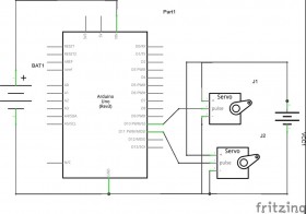
Arduino dapat digunakan untuk mengendalikan motor servo. Dalam beberapa contoh, servo dan Arduino menggunakan sumber daya yang sama. Sumber daya di sini bisa berupa batere, bisa juga berupa daya dari konektor USB ke PC. Contoh skema rangkaian dengan sumber daya tunggal dapat dilihat pada gambar berikut:
Rangkaian Arduino dengan 1 sumber daya
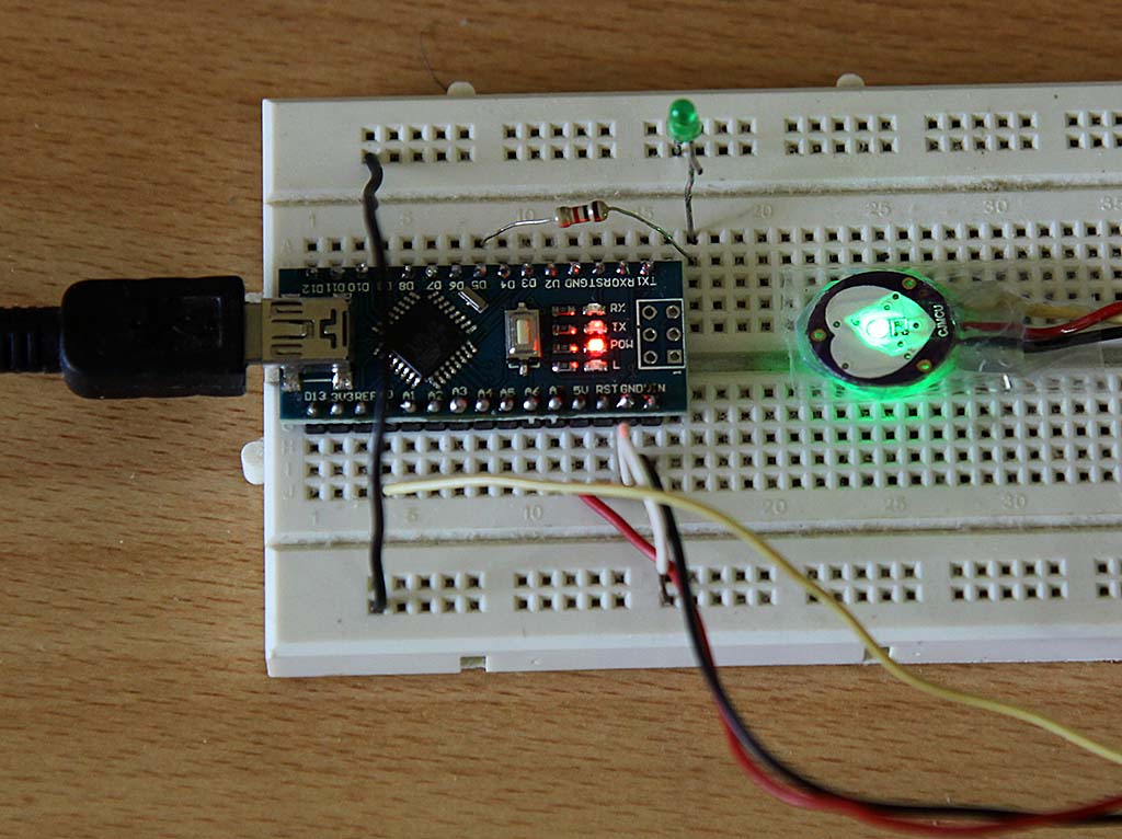
Arduino Nano dengan sumber daya dari port USB
Dalam prakteknya, sering dijumpai Arduino bermasalah ketika motor servo menggunakan sumber daya yang sama dengan Arduino. Gejalanya yang sering terjadi antara lain tidak dapat melakukan upload program ke Arduino, namun dapat berfungsi normal kalau motor servo dicopot dulu.
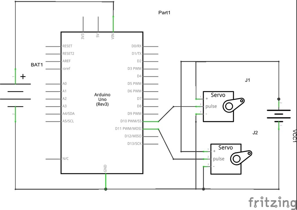
Solusinya adalah dengan menggunakan 2 buah sumber daya yang berbeda, satu untuk board Arduino, satu lagi untuk motor servo.
Contoh rangkaian dapat dilihat pada gambar berikut ini.
Rangkaian Arduino dengan 2 batere
Alasan menggunakan 2 batere:
Beberapa tipe motor servo ketika bergerak mengambil arus cukup banyak dari batere, sehingga tegangan batere dapat turun dari tegangan normalnya. Jika batere yang sama digunakan untuk Arduino dan motor, maka penurunan tegangan akibat motor servo tersebut dapat mengganggu kerja prosesor, ekstrimnya prosesor akan mengalami reset / hang.
Beberapa motor servo dapat bekerja lebih kuat jika diberi tegangan agak besar, misal HS311 dapat mempunyai torsi besar jika diberi tegangan 6 volt. Dalam hal ini kita dapat menggunakan batere 5 volt untuk board Arduino, dan batere 6 volt untuk motor servo
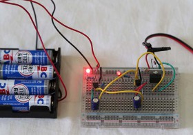
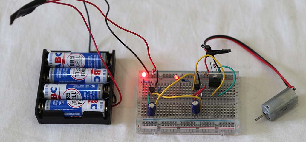
Percobaan membuat pengatur motor on-off dengan rangkaian astable multivibrator. Bisa juga pakai IC 555 sih, namun sekali-sekali ingin juga dengan cara lain.
Berikut ini foto rangkaian, batere 4×1.5 volt dan motor DC yang dikendalikan.
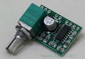
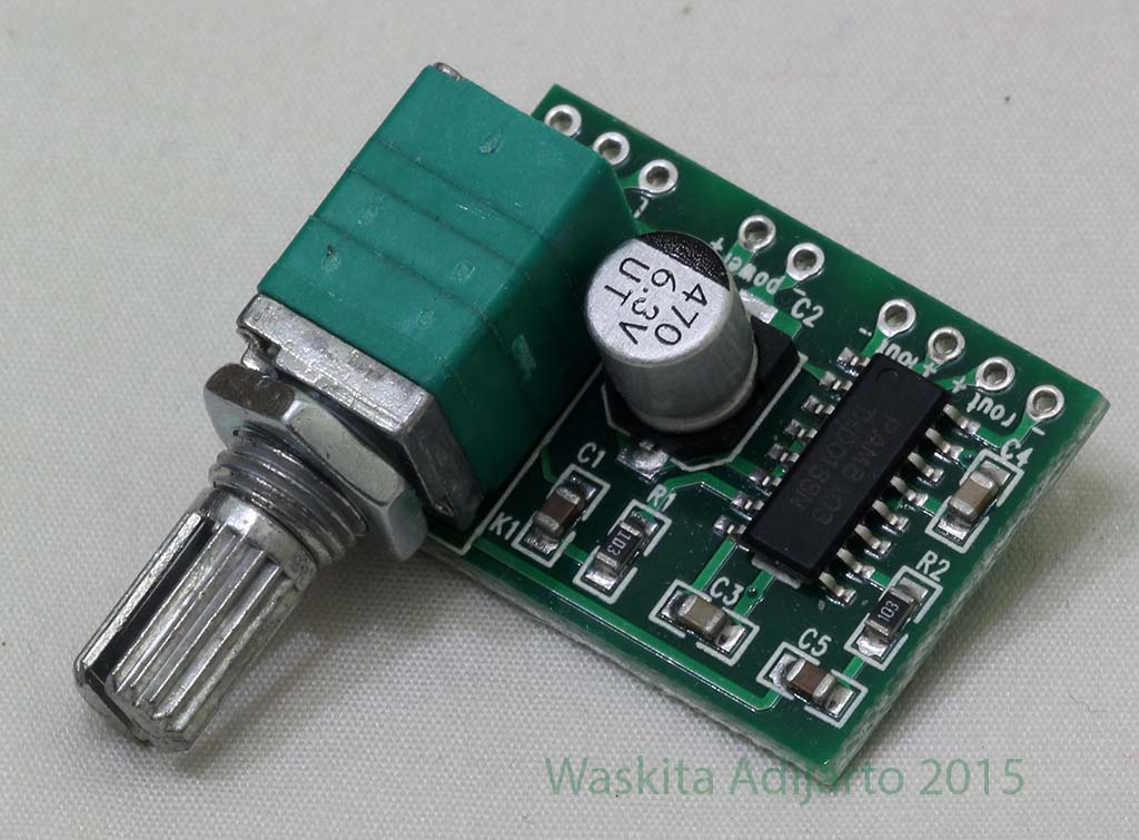
PAM8403 Amplifier Kelas DPAM8403 Amplifier Kelas D
Deskripsi
The PAM8403 is a 3W, class-D audio amplifier. It offers low THD+N,
allowing it to achieve high-quality sound reproduction. The new
filterless architecture allows the device to drive the speaker directly,
requiring no low-pass output filters, thus saving system cost and PCB
area.
With the same numbers of external components, the efficiency of the
PAM8403 is much better than that of Class-AB cousins. It can extend
the battery life, which makes it well-suited for portable applications.
The PAM8403 is available in SOP-16 package.
Feature
3W Output at 10% THD with a 4Ω Load and 5V Power Supply
Filterless, Low Quiescent Current and Low EMI
Low THD+N
Superior Low Noise
Efficiency up to 90%
Short Circuit Protection
Thermal Shutdown
Few External Components to Save the Space and Cost
Pb-Free Package
Aplikasi
LCD Monitors / TV Projectors
Notebook Computers
Portable Speakers
Portable DVD Players, Game Machines
Cellular Phones/Speaker Phones
Typical Application Circuit
Rangkaian PAM8403
Daftar Pin
Nomor Pin
Nama Pin
Fungsi
1
+OUT_L
Left Channel Positive Output
2
PGND
Power GND
3
-OUT_L
Left Channel Negative Output
4
PVDD
Power VDD
5
MUTE
Mute Control Input (active low)
6
VDD
Analog VDD
7
INL
Left Channel Input
8
VREF
Internal analog reference, connect a bypass capacitor from VREF to GND.
9
NC
No Connact
10
INR
Right Channel Input
11
GND
Analog GND
12
SHND
Shutdown Control Input (active low)
13
PVDD
Power VDD
14
-OUT_R
Right Channel Negative Output
15
PGND
Power GND
16
+OUT_R
Right Channel Positive Output
Functional Block Diagram
PAM8403 Functional Block Diagram
Absolute Maximum Rating
These are stress ratings only and functional operation is not implied. Exposure to absolute maximum ratings for prolonged time periods may
affect device reliability. All voltages are with respect to ground.