Berikut ini hasil pengukuran output analog dari DAC dengan osiloskop
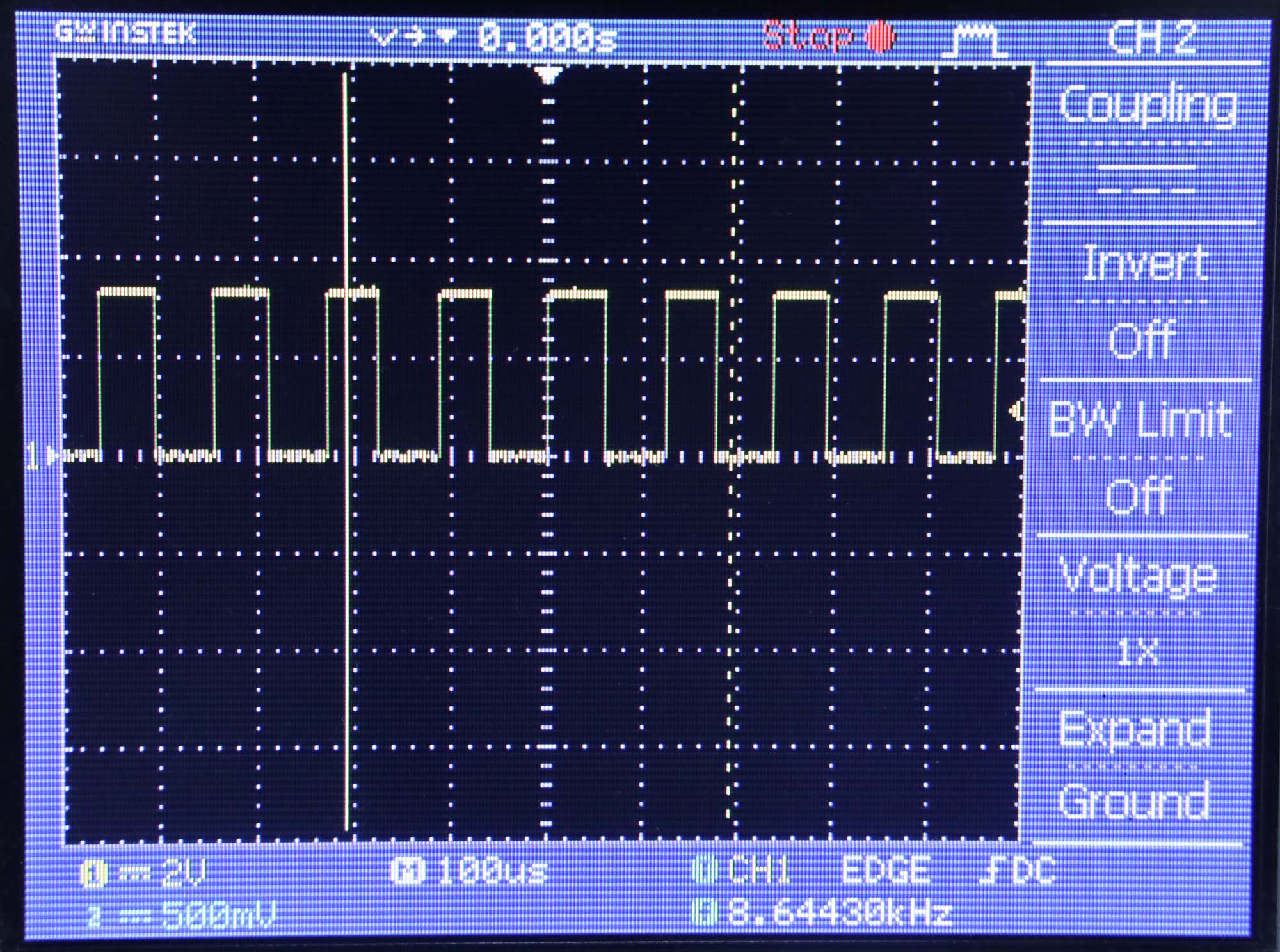
Pengukuran V2
Pada pengukuran ini menggunakan fungsi dac_output_enable() dan dac_output_voltage(). Pada fungsi dacWrite, fungsi dac_output_enable() selalu dipanggil sehingga cukup menghabiskan waktu.
// Profiling kecepatan konversi ADC MCP3008 di ESP32
// menggunakan modified header dari https://github.com/bakercp/MCP3XXX

#include "MCP3XXXZ.h" // custom header

MCP3008 adc;

void setup() {
  Serial.begin(115200);
  Serial.println("start");
  // Use the default SPI hardware interface.
  adc.begin();
  // Or use custom pins to use a software SPI interface.
  // adc.begin(SS, MOSI, MISO, SCK);
  pinMode(22, OUTPUT); // digital output for monitoring
  pinMode(21, OUTPUT);

  adc.spistart(); //
}
int counter = 0, last_time = 0, current_time = 0;
float durasi=0;
int jumlah_iterasi=100000;

void loop() {
  for (;;) {

    digitalWrite(22, HIGH);  // turn the LED on (HIGH is the voltage level)
    adc.analogRead(0);
    digitalWrite(22, LOW);  // turn the LED on (HIGH is the voltage level)

    counter = counter + 1;
    if (counter == jumlah_iterasi) {  // tiap 10000x berhenti
      counter = 0;
      current_time = millis();
      durasi = (float)(current_time - last_time) / (float) jumlah_iterasi;
      Serial.print("durasi (ms) ");
      Serial.println(durasi,4);
      last_time = current_time;
    }
  }
}
Kode header sebagai berikut
//
// Copyright (c) 2018 Christopher Baker <https://christopherbaker.net>
//
// SPDX-License-Identifier:	MIT
//


#pragma once


#include <Arduino.h>
#include <SPI.h>


/// \brief A template class supporting MCP3XXX ADC SPI chips.
///
/// \tparam NumBits Number of ADC bits.
/// \tparam NumChannels Number of input channels.
/// \tparam MaxSPIClockSpeed Maximum SPI communication speed rate in Hz.
/// \tparam SPITransferLength The number of bytes transferred over SPI.
template<uint8_t NumBits,
         uint8_t NumChannels,
         uint32_t MaxSPIClockSpeed,
         uint8_t SPITransferLength = 3>
class MCP3XXX_
{
public:

    enum
    {
        /// \brief ADC error value.
        ADC_ERROR_INVALID_CHANNEL = -1,

        /// \brief ADC error value.
        ADC_UNSUPPORTED_CONFIGURATION = -2,

        /// \brief Number of ADC bits.
        NUM_BITS = NumBits,

        /// \brief A bit mask based on the number of bits.
        BIT_MASK = (1 << NUM_BITS) - 1,

        /// \brief Number of input channels.
        NUM_CHANNELS = NumChannels,

        /// \brief Maximum SPI communication speed rate in Hz.
        MAX_SPI_CLOCK_SPEED = MaxSPIClockSpeed,

        /// \brief The number of bytes transferred over SPI.
        SPI_TRANSFER_LEGNTH = SPITransferLength
    };


    /// \brief Construct a default MCP3XXX_ device.
    MCP3XXX_()
    {
    }

    /// \brief Destroy the MCP3XXX_ device.
    ~MCP3XXX_()
    {
    }

	void spistart(){
		SPI.beginTransaction(SPISettings(MAX_SPI_CLOCK_SPEED, MSBFIRST, SPI_MODE0));
	}
    /// \brief Set up the ADC using default hardware SPI pins.
    ///
    /// Hardware SPI pins vary based on the board being used. These default pins
    /// are represented by the constants SS, MOSI, MISO and SCK.
    ///
    /// \sa https://www.arduino.cc/en/Reference/SPI
    /// \param csPin Chip Select Pin. Default value is SS.
    void begin(uint8_t csPin = SS)
    {
      _useHardwareSPI = true;

      _csPin = csPin;
      _mosiPin = MOSI;
      _misoPin = MISO;
      _sckPin = SCK;

      // Set up pin modes.
      pinMode(_csPin, OUTPUT);

      // Begin software SPI.
      // Initializes the SPI bus by setting SCK, MOSI, and SS to outputs,
      // pulling SCK and MOSI low, and SS high.
      digitalWrite(_csPin, HIGH); // Redundant.
      SPI.begin();
    }

    /// \brief Set up the ADC using custom software SPI pins.
    ///
    /// This method forces the SPI to be accesed via software methods rather
    /// than hardware SPI. This is true, even if the default hardware SPI pins
    /// are used.
    ///
    /// \param csPin Chip Select Pin.
    /// \param mosiPin MOSI pin.
    /// \param misoPin MISO pin.
    /// \param sckPin Clock pin.
    void begin(uint8_t csPin, uint8_t mosiPin, uint8_t misoPin, uint8_t sckPin)
    {
      _useHardwareSPI = false;

      _csPin = csPin;
      _mosiPin = mosiPin;
      _misoPin = misoPin;
      _sckPin = sckPin;

      // Set up pin modes manually.
      pinMode(_csPin, OUTPUT);
      pinMode(_mosiPin, OUTPUT);
      pinMode(_misoPin, INPUT);
      pinMode(_sckPin, OUTPUT);

      // Begin software SPI. We initiate CS Pin HIGH to prepare it to go LOW
      // on our first read.
      digitalWrite(_csPin, HIGH);
    }

    /// \brief Read the analog value.
    ///
    /// Reads a single-ended analog value using the given channel.
    ///
    /// \param channel The channel (channel < NUM_CHANNELS) to read.
    /// \returns values [0, MAX_VALUE) on success or an error code on failure.
    uint32_t analogRead(uint8_t channel) const
    {
        if (channel < NUM_CHANNELS)
          return _read(channel, false);
        return ADC_ERROR_INVALID_CHANNEL;
    }

    /// \brief Read a differential analog value by specifying the IN+ channel.
    ///
    /// Consecutive channel pairs can be differentially read. For instance, if
    /// inPositiveChannel == 0, inNegativeChannel will be 1.
    /// If inPositiveChannel == 1, then inNegativeChannel will be 0. Thus if
    /// inPositiveChannel is odd, inNegativeChannel == (inPositiveChannel - 1).
    /// if inPositiveChannel is even, inNegativeChannel == (inPositiveChannel + 1).
    ///
    /// \param inPositiveChannel The channel that should be input positive.
    /// \returns Differential values. See the data sheet for information on how
    ///          to interpret these return values.
    uint32_t analogReadDifferential(uint8_t inPositiveChannel) const
    {
        if (inPositiveChannel < NUM_CHANNELS)
          return _read(inPositiveChannel, true);
        return ADC_ERROR_INVALID_CHANNEL;
    }

    /// \returns the number of ADC channels.
    size_t numChannels() const
    {
        return NUM_CHANNELS;
    }

    /// \returns the number of ADC bits.
    size_t numBits() const
    {
        return NUM_BITS;
    }

private:
    MCP3XXX_(const MCP3XXX_&);
    MCP3XXX_& operator = (const MCP3XXX_&);

    /// \brief Read the value from the given channel using the given mode.
    /// \param channel The channel to read.
    /// \param differential If true, use differential read mode.
    uint32_t _read(uint8_t channel, bool differential) const
    {
      // Data transfers are done using "8-bit segments" approach in data sheet.
      // The sent data alignment resuls in correctly aligned return bytes after
      // the SPI transfer.
      uint8_t data[SPI_TRANSFER_LEGNTH];

      // Check for MCP3004
      if (NUM_CHANNELS == 2)
      {
        if (NUM_BITS == 10)
        {
          // Start bit.
          data[0] = 0b01000000;
          // Differential bit.
          data[0] |= (differential ? 0b00000000 : 0b00100000);
          // Channel bit.
          data[0] |= (channel == 0 ? 0b00000000 : 0b00010000);
          // MSBF bit is set to 1. See section 5.1 of the data sheet.
          data[0] |= 0b00001000;
          // It doesn't matter what data[1] is set to.
        }
        else
        {
          return ADC_UNSUPPORTED_CONFIGURATION;
        }
      }
      else
      {
        if (NUM_BITS == 10)
        {
          // The start bit. We position it here to align our output data.
          data[0] = 0b00000001;
          // Set the differential / single bit and the channel bits.
          data[1] = (differential ? 0b00000000 : 0b10000000) | (channel << 4);
          // It doesn't matter what data[2] is set to.
        }
        else
        {
          return ADC_UNSUPPORTED_CONFIGURATION;
        }
      }

      if (_useHardwareSPI)
      {
        // Here we replace the sent data with the received data.
//        SPI.beginTransaction(SPISettings(MAX_SPI_CLOCK_SPEED, MSBFIRST, SPI_MODE0));
//		digitalWrite(21, HIGH);  // turn the LED on (HIGH is the voltage level)
        digitalWrite(_csPin, LOW);
        for (size_t i = 0; i < SPI_TRANSFER_LEGNTH; ++i)
        {
          data[i] = SPI.transfer(data[i]);
        }
        digitalWrite(_csPin, HIGH);
//		digitalWrite(21, LOW);  // turn the LED on (HIGH is the voltage level)
//        SPI.endTransaction();
      }
      else
      {
        // Slower, but can use any pin.
        // We could save a few operations by skipping some digitalWrites(),
        // using bitwise operators and doing direct port-manipulation.
        // But this is used because it is "easier" to read.
        digitalWrite(_csPin, LOW);
        for (size_t i = 0; i < SPI_TRANSFER_LEGNTH; ++i)
        {
          for (size_t j = 8; j-- > 0;)
          {
            // Set MOSI data.
            digitalWrite(_mosiPin, bitRead(data[i], j));
            // Set Clock HIGH.
            digitalWrite(_sckPin, HIGH);
            // Read MISO data.
            bitWrite(data[i], j, digitalRead(_misoPin));
            // Set Clock LOW.
            digitalWrite(_sckPin, LOW);
          }
        }
        digitalWrite(_csPin, HIGH);
      }

      // Here we take the second two bytes returned as our value.
      // This value is already correctly aligned since we are using the 8-bit
      // segments approach. The BIT_MASK is calculated based on the number out
      // bits specified in the template parameters.
      return ((data[SPI_TRANSFER_LEGNTH - 2] << 8) | data[SPI_TRANSFER_LEGNTH - 1]) & BIT_MASK;
    }


    /// \brief Use hardware SPI to communicate.
    bool _useHardwareSPI = true;

    /// \brief Chip Select pin.
    uint8_t _csPin = SS;

    /// \brief MOSI pin.
    uint8_t _mosiPin = MOSI;

    /// \brief MISO pin.
    uint8_t _misoPin = MISO;

    /// \brief SCLK pin.
    uint8_t _sckPin = SCK;

};

/// \brief A typedef for the MCP3002.
/// Max clock frequency for 2.7V: 1200000 Hz
/// Max clock frequency for 5.0V: 3200000 Hz
/// \sa http://ww1.microchip.com/downloads/en/DeviceDoc/21294E.pdf
typedef MCP3XXX_<10, 2, 1200000, 2> MCP3002;

/// \brief A typedef for the MCP3004.
/// Max clock frequency for 2.7V: 1350000 Hz
/// Max clock frequency for 5.0V: 3600000 Hz
/// \sa http://ww1.microchip.com/downloads/en/DeviceDoc/21295C.pdf
typedef MCP3XXX_<10, 4, 1350000> MCP3004;

/// \brief A typedef for the MCP3008.
/// Max clock frequency for 2.7V: 1350000 Hz
/// Max clock frequency for 5.0V: 3600000 Hz
/// \sa http://ww1.microchip.com/downloads/en/DeviceDoc/21295C.pdf
//typedef MCP3XXX_<10, 8, 1350000> MCP3008;
typedef MCP3XXX_<10, 8, 3000000> MCP3008;

// /// \brief A typedef for the MCP3202.
// /// Max clock frequency for 2.7V:  900000 Hz
// /// Max clock frequency for 5.0V: 1800000 Hz
// /// \sa http://ww1.microchip.com/downloads/en/DeviceDoc/21034D.pdf
// typedef MCP3XXX_<12, 2, 900000> MCP3202;
//
// /// \brief A typedef for the MCP3204.
// /// Max clock frequency for 2.7V: 1000000 Hz
// /// Max clock frequency for 5.0V: 2000000 Hz
// /// \sa http://ww1.microchip.com/downloads/en/DeviceDoc/21298c.pdf
// typedef MCP3XXX_<12, 4, 1000000> MCP3204;
//
// /// \brief A typedef for the MCP3208.
// /// Max clock frequency for 2.7V: 1000000 Hz
// /// Max clock frequency for 5.0V: 2000000 Hz
// /// \sa http://ww1.microchip.com/downloads/en/DeviceDoc/21298c.pdf
// typedef MCP3XXX_<12, 8, 1000000> MCP3208;
//
// /// \brief A typedef for the MCP3208.
// /// Max clock frequency for 2.7V: 1050000 Hz
// /// Max clock frequency for 5.0V: 2100000 Hz
// /// \sa http://ww1.microchip.com/downloads/en/DeviceDoc/21697e.pdf
// typedef MCP3XXX_<13, 8, 1050000> MCP3304;
Pengukuran Frekuensi ADC internal pada Arduino Nano ATmega328
berikut ini kode yang dipakai untuk pengukuran
int counter;  // how many iterations
int time_begin = 0;
int time_end = 0;
int duration;

int sensorPin = A0;   // select the input pin for the potentiometer
int ledPin = 13;      // select the pin for the LED

void setup() {
  Serial.begin(115200);
  counter = 0;
  pinMode(2, OUTPUT);
  Serial.println("start benchmark");
}
//---------------------------------------------------
void loop() {
  int value;  // angka yang ditulis
  value = 0;  // minimum value
  analogRead(sensorPin);
  PORTD=0; // langsung akses port supaya lebih cepat
  analogRead(sensorPin);
  PORTD=255;
  counter = counter + 1;
  if (counter >= 10000) {
    float period;
    int time_now = millis();
    counter = 0;
    duration = time_now - time_begin;
    period = duration / 10000.0 /2;
    Serial.print("period (ms): ");
    Serial.println(period);
    //  prepare next round
    time_begin = time_now;
  }
}
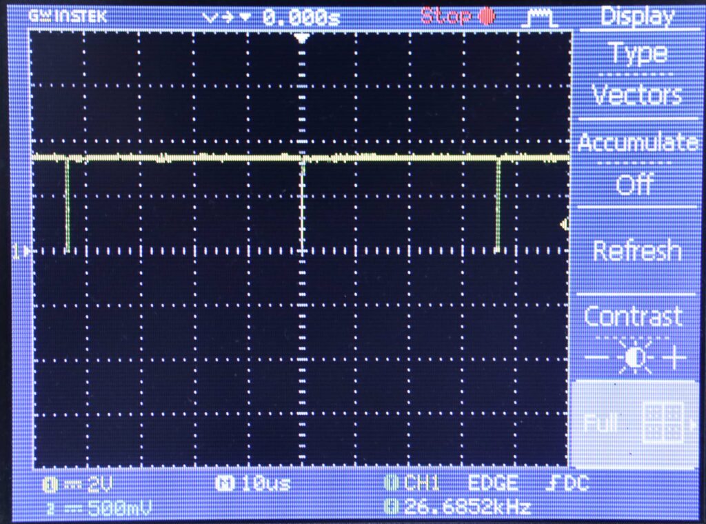
Hasil Pengukuran
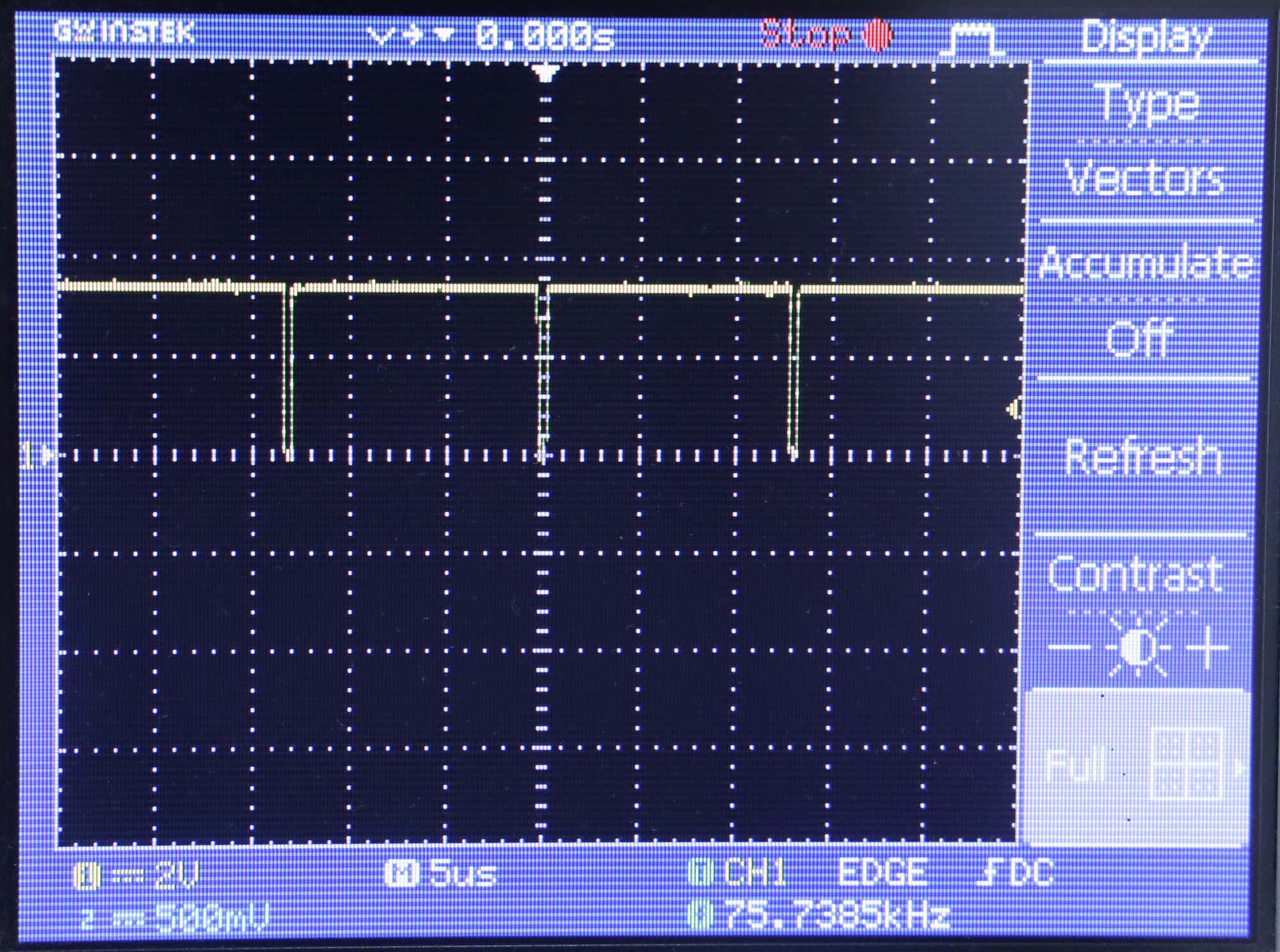
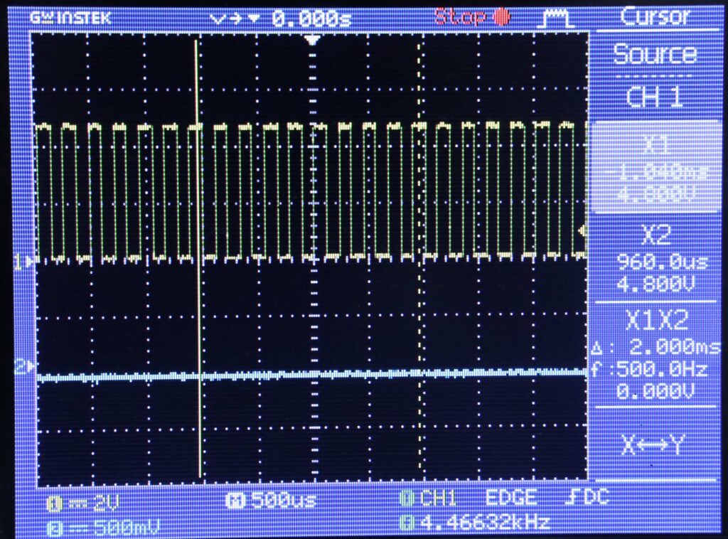
Pengukuran output pada pin D2 dengan osiloskop menghasilkan sinyal berikut
Dari data port serial, didapatkan angka perioda 0,11 ms
start benchmark
period (ms): 0.11
period (ms): 0.11
period (ms): 0.11
period (ms): 0.11
period (ms): 0.11
Dengan osiloskop didapatkan sinyal kotak dengan frekuensi 4,45532 kHz . Artinya frekuensi ADC adalah dua kalinya, yaitu 8,91064 kHz
Angka 8900 Hz ini sesuai dengan pengukuran di artikel lain: https://chisight.wordpress.com/2016/03/25/speeding-up-the-adc-on-an-arduino-atmega-328p/
Kesimpulan
Frekuensi ADC adalah 8,91064 kHz
Frekuensi ini jauh di bawah kecepatan teoritis. Kemungkinan kelambatan karena library yang dipakai.
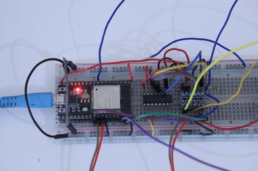
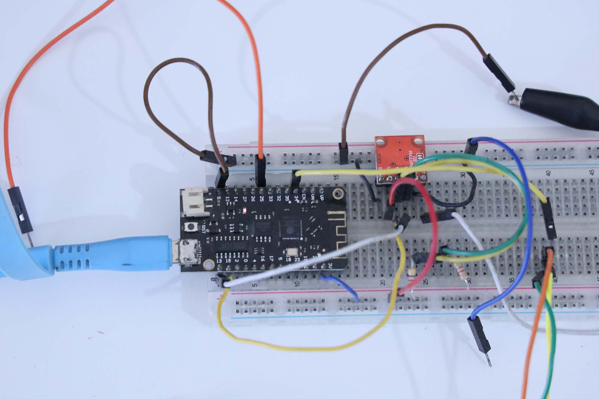
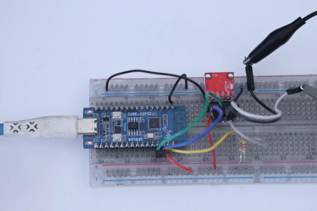
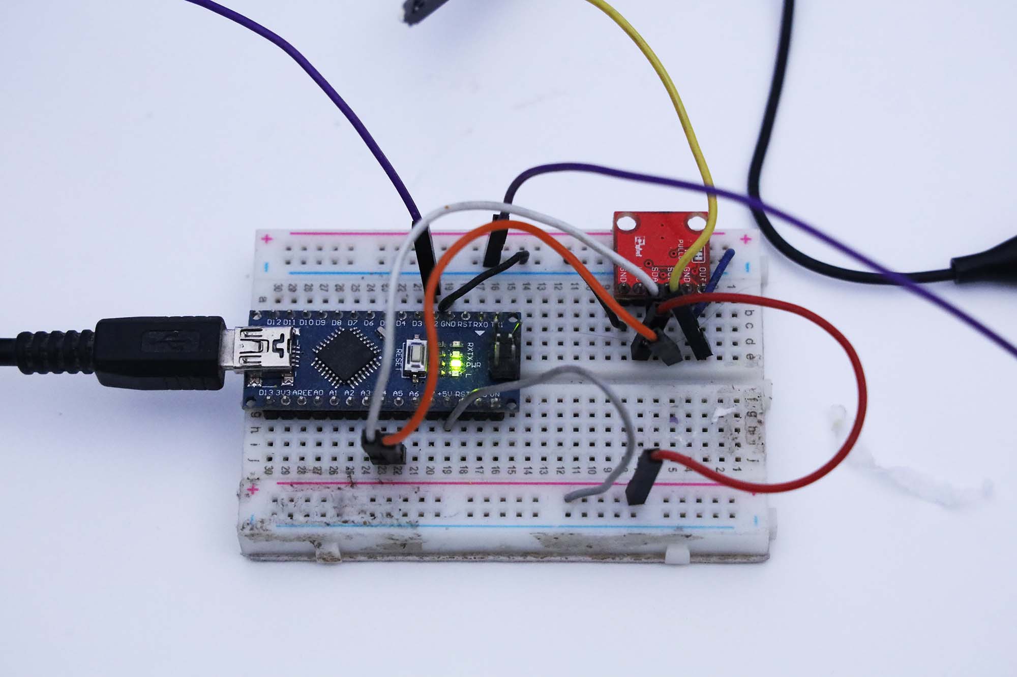
Pada percobaan ini diukur frekuensi & perioda konversi DAC (Digital to Analog Converter) tipe MCP4725 pada modul Arduino Nano dengan prosesor ATmega328.
Rangkaian sistem adalah sebagai berikut
Kode yang dipakai untuk pengujian adalah sebagai berikut:
// idea from https://learn.sparkfun.com/tutorials/mcp4725-digital-to-analog-converter-hookup-guide/all
#define MCP4725_ADDR 0x60
#include <Wire.h>  //Include the Wire library to talk I2C

int counter;  // how many iterations
int time_begin = 0;
int time_end = 0;
int duration;
void setup() {
  Wire.begin();
  Serial.begin(115200);
  counter = 0;
  Serial.println("start benchmark");
}
//---------------------------------------------------
void loop() {
  int value;  // angka yang ditulis
  value = 0;  // minimum value
  Wire.beginTransmission(MCP4725_ADDR);
  Wire.write(64);                 // cmd to update the DAC
  Wire.write(value >> 4);         // the 8 most significant bits...
  Wire.write((value & 15) << 4);  // the 4 least significant bits...
  Wire.endTransmission();

  value = 4095;  // maximum value
  Wire.beginTransmission(MCP4725_ADDR);
  Wire.write(64);                 // cmd to update the DAC
  Wire.write(value >> 4);         // the 8 most significant bits...
  Wire.write((value & 15) << 4);  // the 4 least significant bits...
  Wire.endTransmission();

  counter = counter + 1;
  if (counter >= 10000) {
    float  period;
    int time_now = millis();
      counter = 0;
    duration = time_now - time_begin;
    period = duration / 10000.0 / 2.0 ;
    Serial.print("period (ms): ");
    Serial.println(period);
    //  prepare next round
    time_begin = time_now;
  }
}
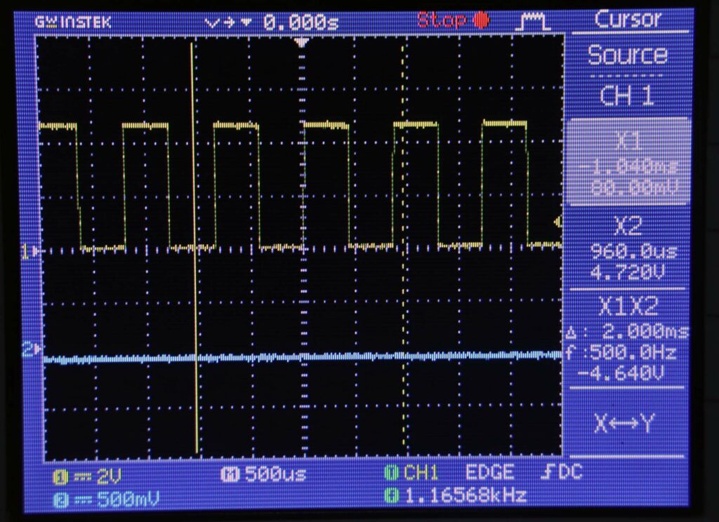
I2C 100 kHz
ATmega328 menggunakan 2 frekuensi I2C: 100 kHz dan 400 kHz. Percoban pertama menggunakan kecepatan default adalah 100 kHz.
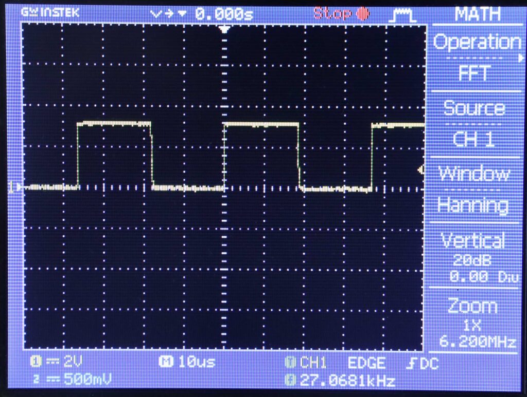
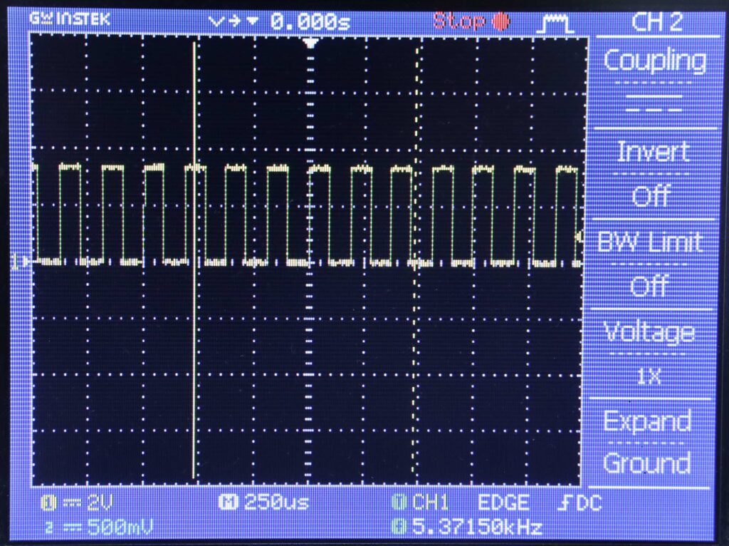
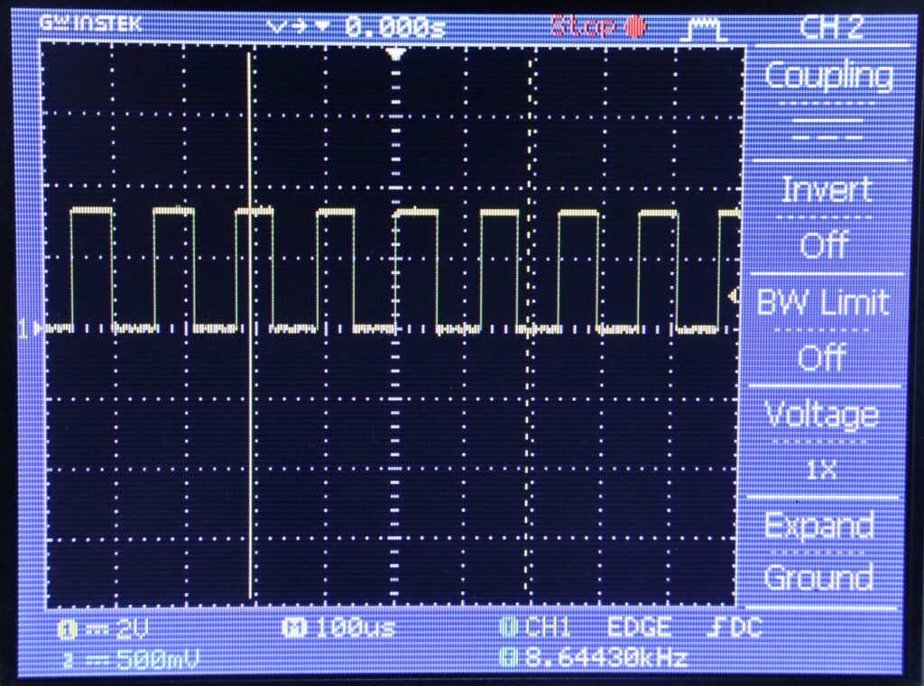
Sinyal yang dihasilkan pada output MCP4725 adalah sebagai berikut:
Tampilan pada serial monitor adalah sebagai berikut:
start benchmark
period (ms): 0.43
period (ms): 0.43
period (ms): 0.43
period (ms): 0.43
period (ms): 0.43
period (ms): 0.43
Pengukuran dengan osiloskop menunjukkan sinyal persegi dengan frekuensi 1,166 kHz
Jumlah transisi adalah 2x frekuensi ini, jadi frekuensi konversi adalah 1,166 x 2 = 2,332 kHz
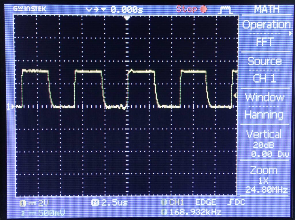
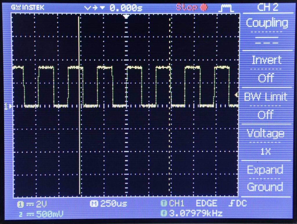
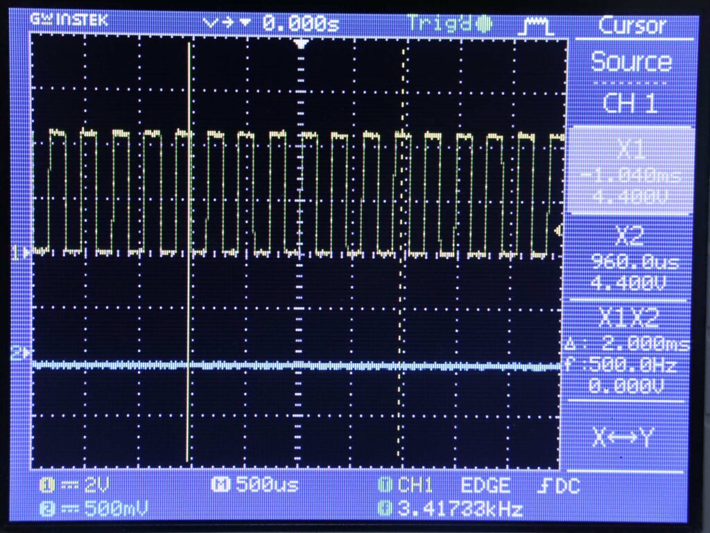
I2C 400 kHz
Pada pengukuran ini, kecepatan I2C dinaikkan menjadi 400 kHz. Caranya menggunakan fungsi Wire.setClock()
Perioda menjadi 0,15 ms
start benchmark
period (ms): 0.15
period (ms): 0.15
period (ms): 0.15
period (ms): 0.15
period (ms): 0.15
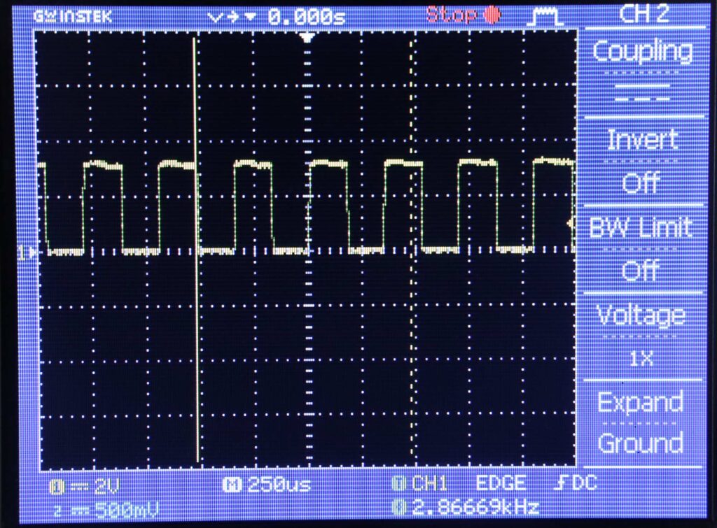
Output DAC diukur dengan osiloskop, dengan hasil sebagai berikut
Frekuensi output adalah 3,41733 kHz, sehingga frekuensi DAC adalah 2x 3,417 = 6,834 kHz