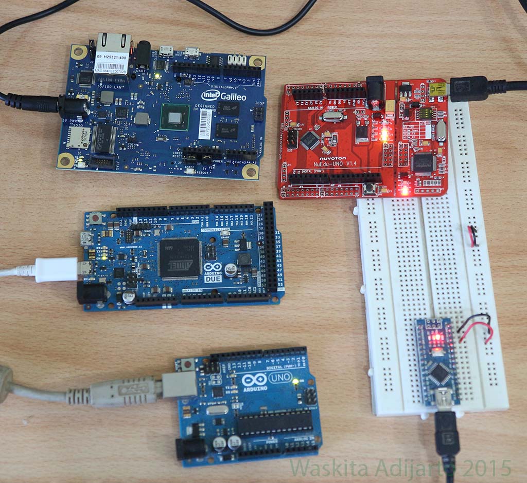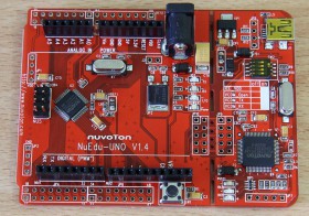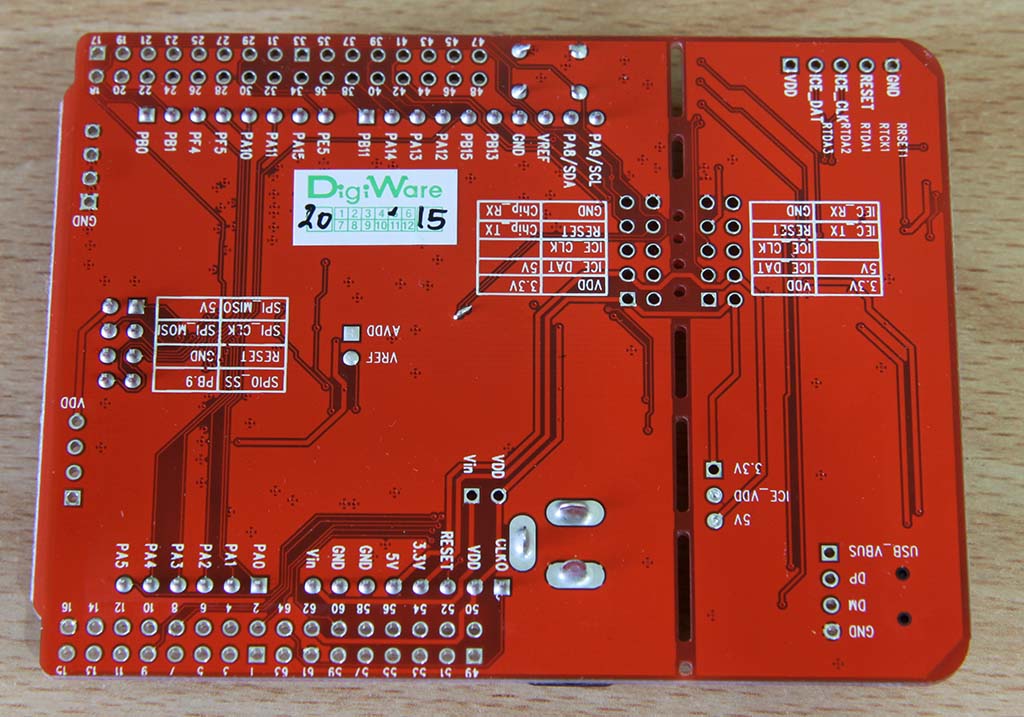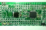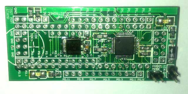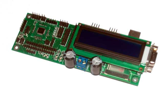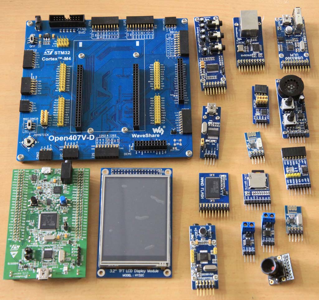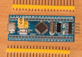
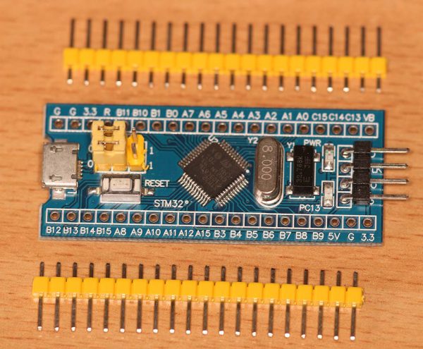
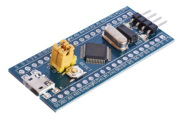
Berikut ini beberapa foto terkait STM32F103. Nantinya akan dilengkapi dengan hasil-hasil percobaan dengan STM32F103
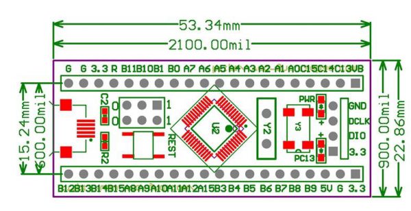
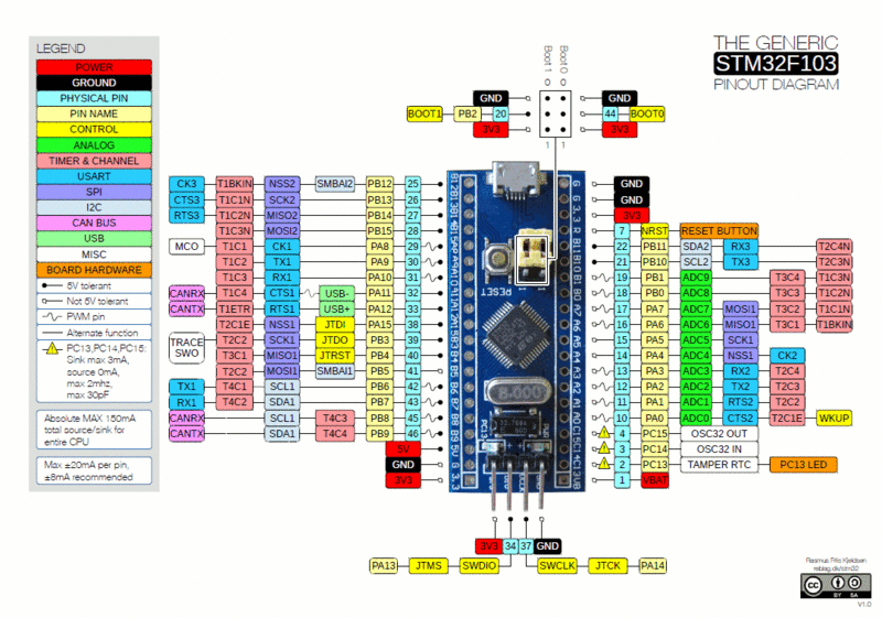
STM32F103 Pinout Diagram
Pemrograman
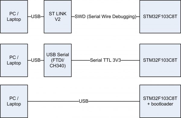
Upload program ke STM32F103 dapat dilakukan dengan 3 cara:
- Menggunakan bootloader internal yang dapat diaktifkan dengan mengubah setting pin BOOT0 menjadi 1. Pada mode ini program dapat dimasukkan menggunakan port serial yang terhubung pada PA9 dan PA10. Port serial pada STM32F103 menggunakan level TTL 3.3 volt, sehingga perlu konverter USB to serial 3V3 supaya dapat dihubungkan ke PC/Laptop.
- Menggunakan pin SWD (Serial Wire Debugging). Untuk programming cara ini mesti menggunakan modul ST LINK V2
- Menggunakan bootloader USB. Bootloader dapat menggunakan port USB untuk memasukkan program sehingga lebih praktis dibandingkan bootloader internal. Bootloader USB ini mesti dimasukkan menggunakan bootloader internal ataupun SWD.
Bootloader
- Serial (TX1/RX1, atau pin PA9 dan PA10) : Built in bootloader yang tersambung ke port serial 1 di STM32F103
- SWD (DIO/DCLK, atau pin JT): STLink v2
- USB (D+/D- atau pin PA11 dan PA12)Custom boot loader, yang dapat dihubungkan ke USB
Untuk memasukkan software dari Windows menggunakan bult in bootloader, dapat menggunakan software Flash Demonstrator dari STMicro http://www.st.com/content/st_com/en/products/development-tools/software-development-tools/stm32-software-development-tools/stm32-programmers/flasher-stm32.html
Salah satu custom boot loader yang sering dipakai adalah STM32duino bootloader, yang memungkinkan pemrograman STM32F103 dengan menggunakan IDE Arduino. Petunjuk instalasinya ada di https://github.com/rogerclarkmelbourne/STM32duino-bootloader
Pengembangan
Pembuatan software untuk STM32 ini dapat dilakukan dengan berbagai cara:
- STM32Duino
- Atollic True Studio https://atollic.com/truestudio/ ukurannya 700 ~ 800 MB
Links:
- TrueStudio https://atollic.com/truestudio/
- Datasheet: http://www.st.com/content/ccc/resource/technical/document/datasheet/33/d4/6f/1d/df/0b/4c/6d/CD00161566.pdf/files/CD00161566.pdf/jcr:content/translations/en.CD00161566.pdf
- 6 IDEs to debut the USD2 STM32 Blue Pill
- Blue Pill http://wiki.stm32duino.com/index.php?title=Blue_Pill
- The most detailed guide on programming and debugging BluePill under Linux with IDE http://www.shortn0tes.com/2017/10/the-most-detailed-guide-on-programming.html
- STM32 Pinout Diagram http://wiki.stm32duino.com/index.php?title=File:Bluepillpinout.gif
- Skematik rangkaian: http://wiki.stm32duino.com/images/c/c1/Vcc-gnd.com-STM32F103C8-schematic.pdf
- STM32F103C8T6 Arduino Guide https://www.techshopbd.com/uploads/product_document/STM32bluepillarduinoguide(1).pdf
- Burning STM32duino bootloader http://wiki.stm32duino.com/index.php?title=Burning_the_bootloader
- STM32 bare metal programming https://satoshinm.github.io/blog/171212_stm32_blue_pill_arm_development_board_first_look_bare_metal_programming.html
- Let’s start with Blue Pill https://jeelabs.org/article/1649a/