
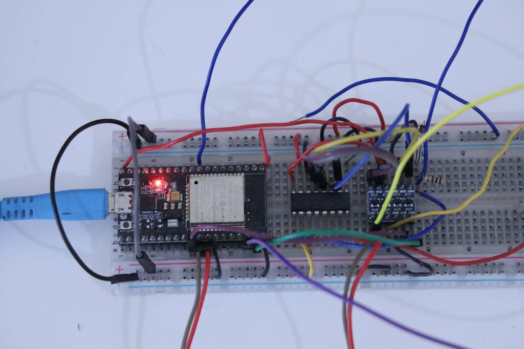
Foto perangkat
// kode
Kode
library yang dipakai untuk MCP3008 adalah https://github.com/bakercp/MCP3XXX
Pengukuran Library Original
Pada pengukuran ini digunakan library https://github.com/bakercp/MCP3XXX tanpa perubahan
Kode ada di https://github.com/waskita/embedded/tree/master/esp32-mcp3008-baker-profile-v1
Kode program adalah sebagai berikut:
// library: https://github.com/bakercp/MCP3XXX
#include <MCP3XXX.h>
MCP3008 adc;
void setup() {
Serial.begin(115200);
Serial.println("start");
// Use the default SPI hardware interface.
adc.begin();
// Or use custom pins to use a software SPI interface.
// adc.begin(SS, MOSI, MISO, SCK);
pinMode(22, OUTPUT); // digital output for monitoring
pinMode(21, OUTPUT);
}
int counter = 0, last_time = 0, current_time = 0;
float durasi=0;
int jumlah_iterasi=100000;
void loop() {
for (;;) {
digitalWrite(22, HIGH); // turn the LED on (HIGH is the voltage level)
adc.analogRead(0);
digitalWrite(22, LOW); // turn the LED on (HIGH is the voltage level)
counter = counter + 1;
if (counter == jumlah_iterasi) { // tiap 10000x berhenti
counter = 0;
current_time = millis();
durasi = (float)(current_time - last_time) / (float) jumlah_iterasi;
Serial.print("durasi (ms) ");
Serial.println(durasi,4);
last_time = current_time;
}
}
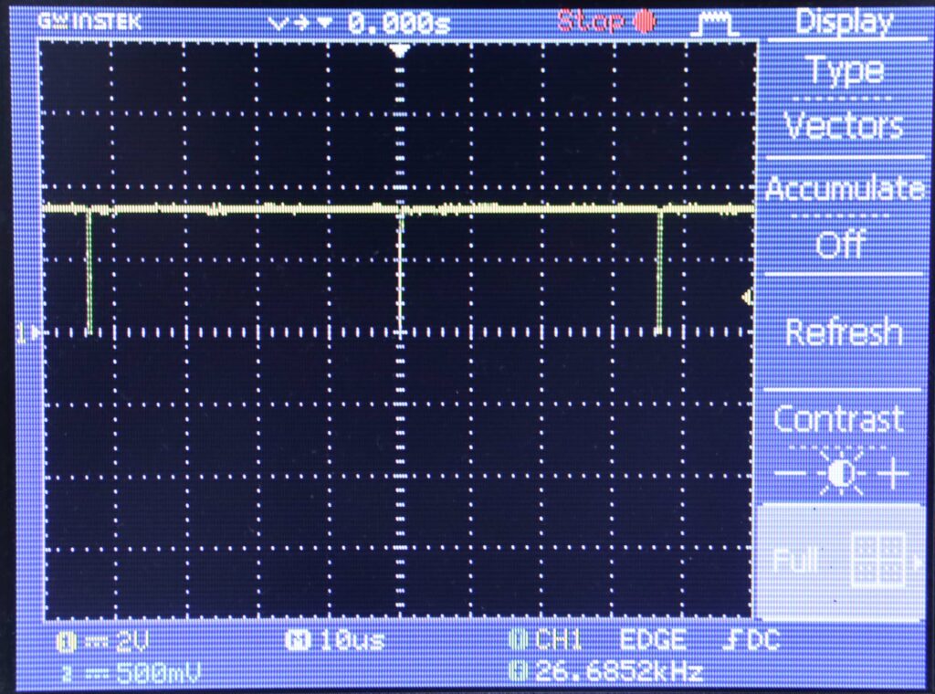
}Hasil pengukuran perioda sebagai berikut
start
durasi (ms) 0.0375
durasi (ms) 0.0370
durasi (ms) 0.0370
Output osiloskop dari output digital sebagai berikut
Pengukuran Library Dimodifikasi
Pada percobaan ini dilakukan perubahan pada library untuk mempercepat proses pembacaan.
Kode ada di https://github.com/waskita/embedded/tree/master/esp32-mcp3008-baker-profile-v2
Kode program utama sebagai berikut:
// Profiling kecepatan konversi ADC MCP3008 di ESP32
// menggunakan modified header dari https://github.com/bakercp/MCP3XXX

#include "MCP3XXXZ.h" // custom header

MCP3008 adc;

void setup() {
  Serial.begin(115200);
  Serial.println("start");
  // Use the default SPI hardware interface.
  adc.begin();
  // Or use custom pins to use a software SPI interface.
  // adc.begin(SS, MOSI, MISO, SCK);
  pinMode(22, OUTPUT); // digital output for monitoring
  pinMode(21, OUTPUT);

  adc.spistart(); //
}
int counter = 0, last_time = 0, current_time = 0;
float durasi=0;
int jumlah_iterasi=100000;

void loop() {
  for (;;) {

    digitalWrite(22, HIGH);  // turn the LED on (HIGH is the voltage level)
    adc.analogRead(0);
    digitalWrite(22, LOW);  // turn the LED on (HIGH is the voltage level)

    counter = counter + 1;
    if (counter == jumlah_iterasi) {  // tiap 10000x berhenti
      counter = 0;
      current_time = millis();
      durasi = (float)(current_time - last_time) / (float) jumlah_iterasi;
      Serial.print("durasi (ms) ");
      Serial.println(durasi,4);
      last_time = current_time;
    }
  }
}
Kode header sebagai berikut
//
// Copyright (c) 2018 Christopher Baker <https://christopherbaker.net>
//
// SPDX-License-Identifier:	MIT
//


#pragma once


#include <Arduino.h>
#include <SPI.h>


/// \brief A template class supporting MCP3XXX ADC SPI chips.
///
/// \tparam NumBits Number of ADC bits.
/// \tparam NumChannels Number of input channels.
/// \tparam MaxSPIClockSpeed Maximum SPI communication speed rate in Hz.
/// \tparam SPITransferLength The number of bytes transferred over SPI.
template<uint8_t NumBits,
         uint8_t NumChannels,
         uint32_t MaxSPIClockSpeed,
         uint8_t SPITransferLength = 3>
class MCP3XXX_
{
public:

    enum
    {
        /// \brief ADC error value.
        ADC_ERROR_INVALID_CHANNEL = -1,

        /// \brief ADC error value.
        ADC_UNSUPPORTED_CONFIGURATION = -2,

        /// \brief Number of ADC bits.
        NUM_BITS = NumBits,

        /// \brief A bit mask based on the number of bits.
        BIT_MASK = (1 << NUM_BITS) - 1,

        /// \brief Number of input channels.
        NUM_CHANNELS = NumChannels,

        /// \brief Maximum SPI communication speed rate in Hz.
        MAX_SPI_CLOCK_SPEED = MaxSPIClockSpeed,

        /// \brief The number of bytes transferred over SPI.
        SPI_TRANSFER_LEGNTH = SPITransferLength
    };


    /// \brief Construct a default MCP3XXX_ device.
    MCP3XXX_()
    {
    }

    /// \brief Destroy the MCP3XXX_ device.
    ~MCP3XXX_()
    {
    }

	void spistart(){
		SPI.beginTransaction(SPISettings(MAX_SPI_CLOCK_SPEED, MSBFIRST, SPI_MODE0));
	}
    /// \brief Set up the ADC using default hardware SPI pins.
    ///
    /// Hardware SPI pins vary based on the board being used. These default pins
    /// are represented by the constants SS, MOSI, MISO and SCK.
    ///
    /// \sa https://www.arduino.cc/en/Reference/SPI
    /// \param csPin Chip Select Pin. Default value is SS.
    void begin(uint8_t csPin = SS)
    {
      _useHardwareSPI = true;

      _csPin = csPin;
      _mosiPin = MOSI;
      _misoPin = MISO;
      _sckPin = SCK;

      // Set up pin modes.
      pinMode(_csPin, OUTPUT);

      // Begin software SPI.
      // Initializes the SPI bus by setting SCK, MOSI, and SS to outputs,
      // pulling SCK and MOSI low, and SS high.
      digitalWrite(_csPin, HIGH); // Redundant.
      SPI.begin();
    }

    /// \brief Set up the ADC using custom software SPI pins.
    ///
    /// This method forces the SPI to be accesed via software methods rather
    /// than hardware SPI. This is true, even if the default hardware SPI pins
    /// are used.
    ///
    /// \param csPin Chip Select Pin.
    /// \param mosiPin MOSI pin.
    /// \param misoPin MISO pin.
    /// \param sckPin Clock pin.
    void begin(uint8_t csPin, uint8_t mosiPin, uint8_t misoPin, uint8_t sckPin)
    {
      _useHardwareSPI = false;

      _csPin = csPin;
      _mosiPin = mosiPin;
      _misoPin = misoPin;
      _sckPin = sckPin;

      // Set up pin modes manually.
      pinMode(_csPin, OUTPUT);
      pinMode(_mosiPin, OUTPUT);
      pinMode(_misoPin, INPUT);
      pinMode(_sckPin, OUTPUT);

      // Begin software SPI. We initiate CS Pin HIGH to prepare it to go LOW
      // on our first read.
      digitalWrite(_csPin, HIGH);
    }

    /// \brief Read the analog value.
    ///
    /// Reads a single-ended analog value using the given channel.
    ///
    /// \param channel The channel (channel < NUM_CHANNELS) to read.
    /// \returns values [0, MAX_VALUE) on success or an error code on failure.
    uint32_t analogRead(uint8_t channel) const
    {
        if (channel < NUM_CHANNELS)
          return _read(channel, false);
        return ADC_ERROR_INVALID_CHANNEL;
    }

    /// \brief Read a differential analog value by specifying the IN+ channel.
    ///
    /// Consecutive channel pairs can be differentially read. For instance, if
    /// inPositiveChannel == 0, inNegativeChannel will be 1.
    /// If inPositiveChannel == 1, then inNegativeChannel will be 0. Thus if
    /// inPositiveChannel is odd, inNegativeChannel == (inPositiveChannel - 1).
    /// if inPositiveChannel is even, inNegativeChannel == (inPositiveChannel + 1).
    ///
    /// \param inPositiveChannel The channel that should be input positive.
    /// \returns Differential values. See the data sheet for information on how
    ///          to interpret these return values.
    uint32_t analogReadDifferential(uint8_t inPositiveChannel) const
    {
        if (inPositiveChannel < NUM_CHANNELS)
          return _read(inPositiveChannel, true);
        return ADC_ERROR_INVALID_CHANNEL;
    }

    /// \returns the number of ADC channels.
    size_t numChannels() const
    {
        return NUM_CHANNELS;
    }

    /// \returns the number of ADC bits.
    size_t numBits() const
    {
        return NUM_BITS;
    }

private:
    MCP3XXX_(const MCP3XXX_&);
    MCP3XXX_& operator = (const MCP3XXX_&);

    /// \brief Read the value from the given channel using the given mode.
    /// \param channel The channel to read.
    /// \param differential If true, use differential read mode.
    uint32_t _read(uint8_t channel, bool differential) const
    {
      // Data transfers are done using "8-bit segments" approach in data sheet.
      // The sent data alignment resuls in correctly aligned return bytes after
      // the SPI transfer.
      uint8_t data[SPI_TRANSFER_LEGNTH];

      // Check for MCP3004
      if (NUM_CHANNELS == 2)
      {
        if (NUM_BITS == 10)
        {
          // Start bit.
          data[0] = 0b01000000;
          // Differential bit.
          data[0] |= (differential ? 0b00000000 : 0b00100000);
          // Channel bit.
          data[0] |= (channel == 0 ? 0b00000000 : 0b00010000);
          // MSBF bit is set to 1. See section 5.1 of the data sheet.
          data[0] |= 0b00001000;
          // It doesn't matter what data[1] is set to.
        }
        else
        {
          return ADC_UNSUPPORTED_CONFIGURATION;
        }
      }
      else
      {
        if (NUM_BITS == 10)
        {
          // The start bit. We position it here to align our output data.
          data[0] = 0b00000001;
          // Set the differential / single bit and the channel bits.
          data[1] = (differential ? 0b00000000 : 0b10000000) | (channel << 4);
          // It doesn't matter what data[2] is set to.
        }
        else
        {
          return ADC_UNSUPPORTED_CONFIGURATION;
        }
      }

      if (_useHardwareSPI)
      {
        // Here we replace the sent data with the received data.
//        SPI.beginTransaction(SPISettings(MAX_SPI_CLOCK_SPEED, MSBFIRST, SPI_MODE0));
//		digitalWrite(21, HIGH);  // turn the LED on (HIGH is the voltage level)
        digitalWrite(_csPin, LOW);
        for (size_t i = 0; i < SPI_TRANSFER_LEGNTH; ++i)
        {
          data[i] = SPI.transfer(data[i]);
        }
        digitalWrite(_csPin, HIGH);
//		digitalWrite(21, LOW);  // turn the LED on (HIGH is the voltage level)
//        SPI.endTransaction();
      }
      else
      {
        // Slower, but can use any pin.
        // We could save a few operations by skipping some digitalWrites(),
        // using bitwise operators and doing direct port-manipulation.
        // But this is used because it is "easier" to read.
        digitalWrite(_csPin, LOW);
        for (size_t i = 0; i < SPI_TRANSFER_LEGNTH; ++i)
        {
          for (size_t j = 8; j-- > 0;)
          {
            // Set MOSI data.
            digitalWrite(_mosiPin, bitRead(data[i], j));
            // Set Clock HIGH.
            digitalWrite(_sckPin, HIGH);
            // Read MISO data.
            bitWrite(data[i], j, digitalRead(_misoPin));
            // Set Clock LOW.
            digitalWrite(_sckPin, LOW);
          }
        }
        digitalWrite(_csPin, HIGH);
      }

      // Here we take the second two bytes returned as our value.
      // This value is already correctly aligned since we are using the 8-bit
      // segments approach. The BIT_MASK is calculated based on the number out
      // bits specified in the template parameters.
      return ((data[SPI_TRANSFER_LEGNTH - 2] << 8) | data[SPI_TRANSFER_LEGNTH - 1]) & BIT_MASK;
    }


    /// \brief Use hardware SPI to communicate.
    bool _useHardwareSPI = true;

    /// \brief Chip Select pin.
    uint8_t _csPin = SS;

    /// \brief MOSI pin.
    uint8_t _mosiPin = MOSI;

    /// \brief MISO pin.
    uint8_t _misoPin = MISO;

    /// \brief SCLK pin.
    uint8_t _sckPin = SCK;

};

/// \brief A typedef for the MCP3002.
/// Max clock frequency for 2.7V: 1200000 Hz
/// Max clock frequency for 5.0V: 3200000 Hz
/// \sa http://ww1.microchip.com/downloads/en/DeviceDoc/21294E.pdf
typedef MCP3XXX_<10, 2, 1200000, 2> MCP3002;

/// \brief A typedef for the MCP3004.
/// Max clock frequency for 2.7V: 1350000 Hz
/// Max clock frequency for 5.0V: 3600000 Hz
/// \sa http://ww1.microchip.com/downloads/en/DeviceDoc/21295C.pdf
typedef MCP3XXX_<10, 4, 1350000> MCP3004;

/// \brief A typedef for the MCP3008.
/// Max clock frequency for 2.7V: 1350000 Hz
/// Max clock frequency for 5.0V: 3600000 Hz
/// \sa http://ww1.microchip.com/downloads/en/DeviceDoc/21295C.pdf
//typedef MCP3XXX_<10, 8, 1350000> MCP3008;
typedef MCP3XXX_<10, 8, 3000000> MCP3008;

// /// \brief A typedef for the MCP3202.
// /// Max clock frequency for 2.7V:  900000 Hz
// /// Max clock frequency for 5.0V: 1800000 Hz
// /// \sa http://ww1.microchip.com/downloads/en/DeviceDoc/21034D.pdf
// typedef MCP3XXX_<12, 2, 900000> MCP3202;
//
// /// \brief A typedef for the MCP3204.
// /// Max clock frequency for 2.7V: 1000000 Hz
// /// Max clock frequency for 5.0V: 2000000 Hz
// /// \sa http://ww1.microchip.com/downloads/en/DeviceDoc/21298c.pdf
// typedef MCP3XXX_<12, 4, 1000000> MCP3204;
//
// /// \brief A typedef for the MCP3208.
// /// Max clock frequency for 2.7V: 1000000 Hz
// /// Max clock frequency for 5.0V: 2000000 Hz
// /// \sa http://ww1.microchip.com/downloads/en/DeviceDoc/21298c.pdf
// typedef MCP3XXX_<12, 8, 1000000> MCP3208;
//
// /// \brief A typedef for the MCP3208.
// /// Max clock frequency for 2.7V: 1050000 Hz
// /// Max clock frequency for 5.0V: 2100000 Hz
// /// \sa http://ww1.microchip.com/downloads/en/DeviceDoc/21697e.pdf
// typedef MCP3XXX_<13, 8, 1050000> MCP3304;
Hasil pengukuran perioda sebagai berikut
start
durasi (ms) 0.0137
durasi (ms) 0.0132
durasi (ms) 0.0132
durasi (ms) 0.0132
Output osiloskop
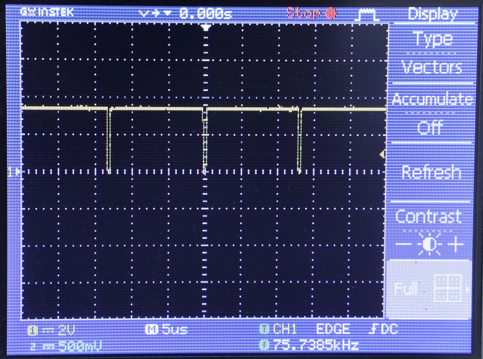
Frekuensi sinyal output sama dengan frekuensi konversi ADC , yaitu 75,739 kHz
Kesimpulan
- Library original menghasilkan frekuensi ADC 26,685 kHz, sedangkan library yang dimodifikasi menghasilkan frekuensi ADC 75,739 kHz
- Library original menghasilkan perioda ADC 0,0370 ms, sedangkan library yang dimodifikasi menghasilkan perioda 0,0132 ms
Referensi
- Library MCP3008 https://github.com/bakercp/MCP3XXX
- ADC untuk Arduino
- ADC dan DAC populer