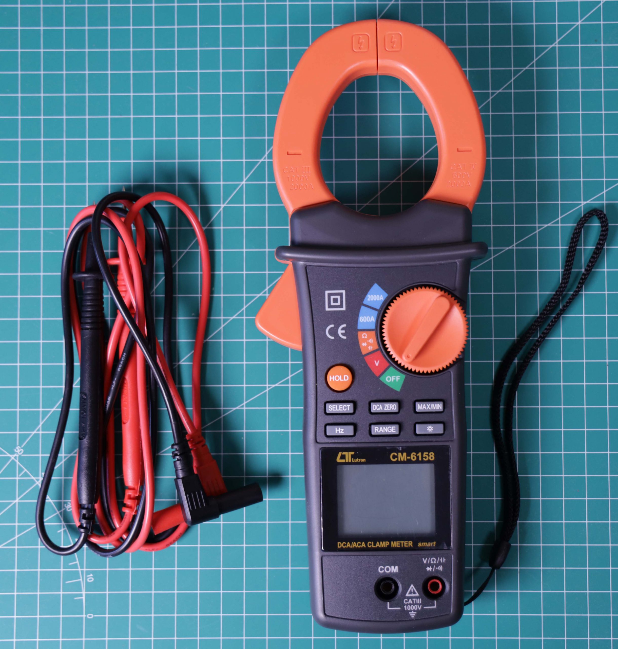
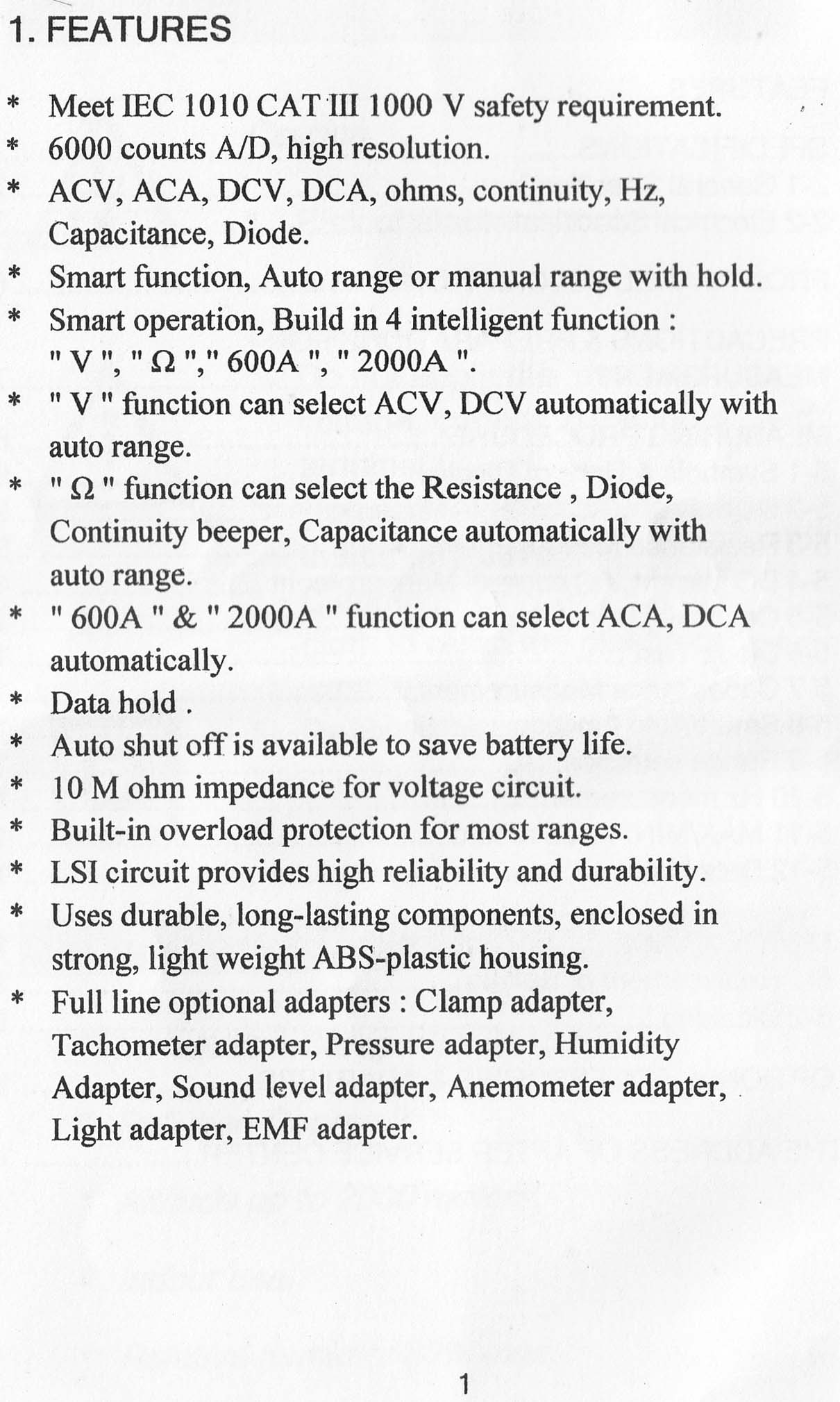
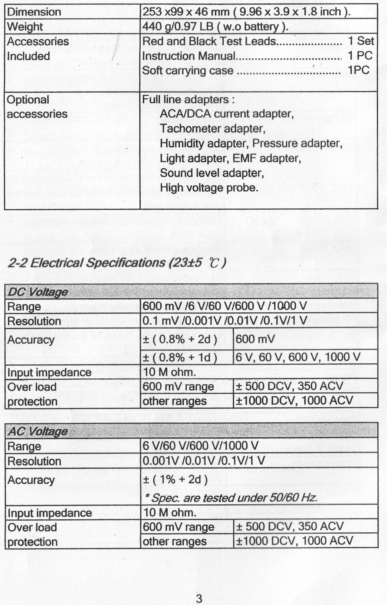
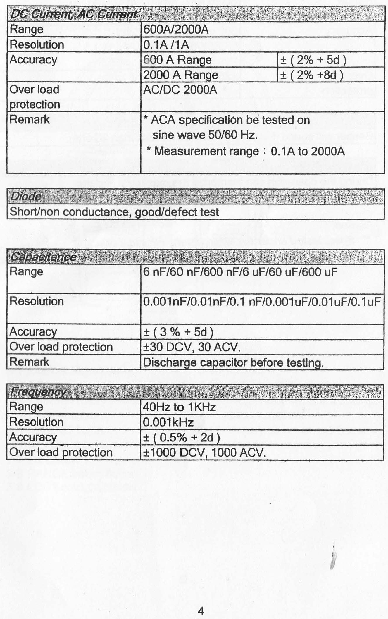
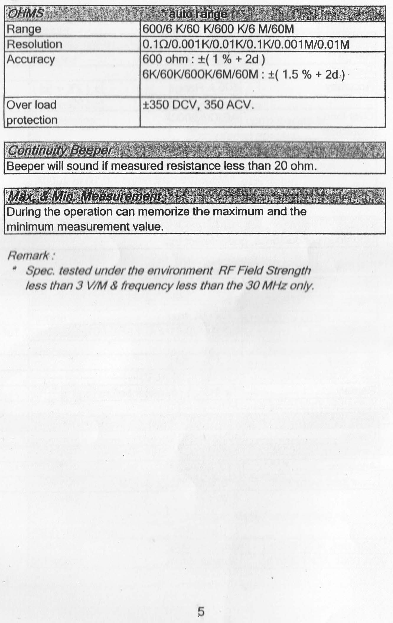
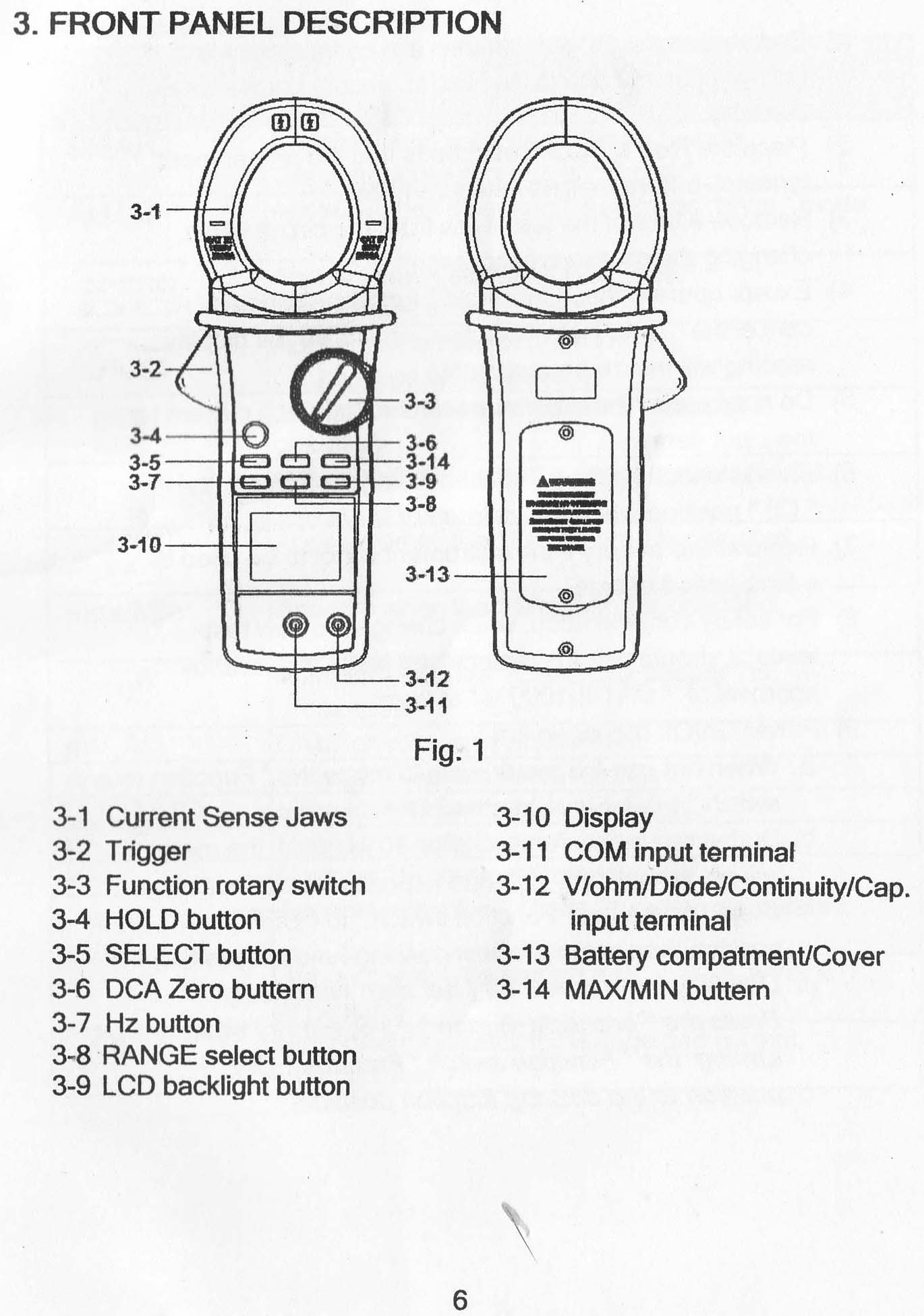
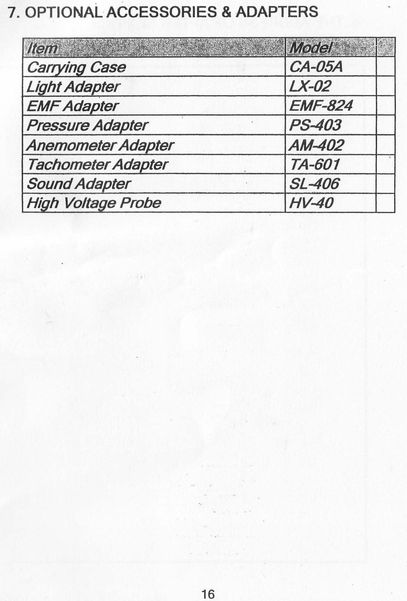
Clamp Meter atau tang ampere model CM-6159 buatan Lutron. Alat ukur ini fungsi utamanya adalah mengukur arus pada sebuah kabel tanpa perlu memutus kabel tersebut. Selain itu alat ukur ini juga dilengkapi dengan pengukuran resistansi (ohm) , kapasitansi, dan tegangan, jadi dapat juga berfungsi seperti multimeter biasa.
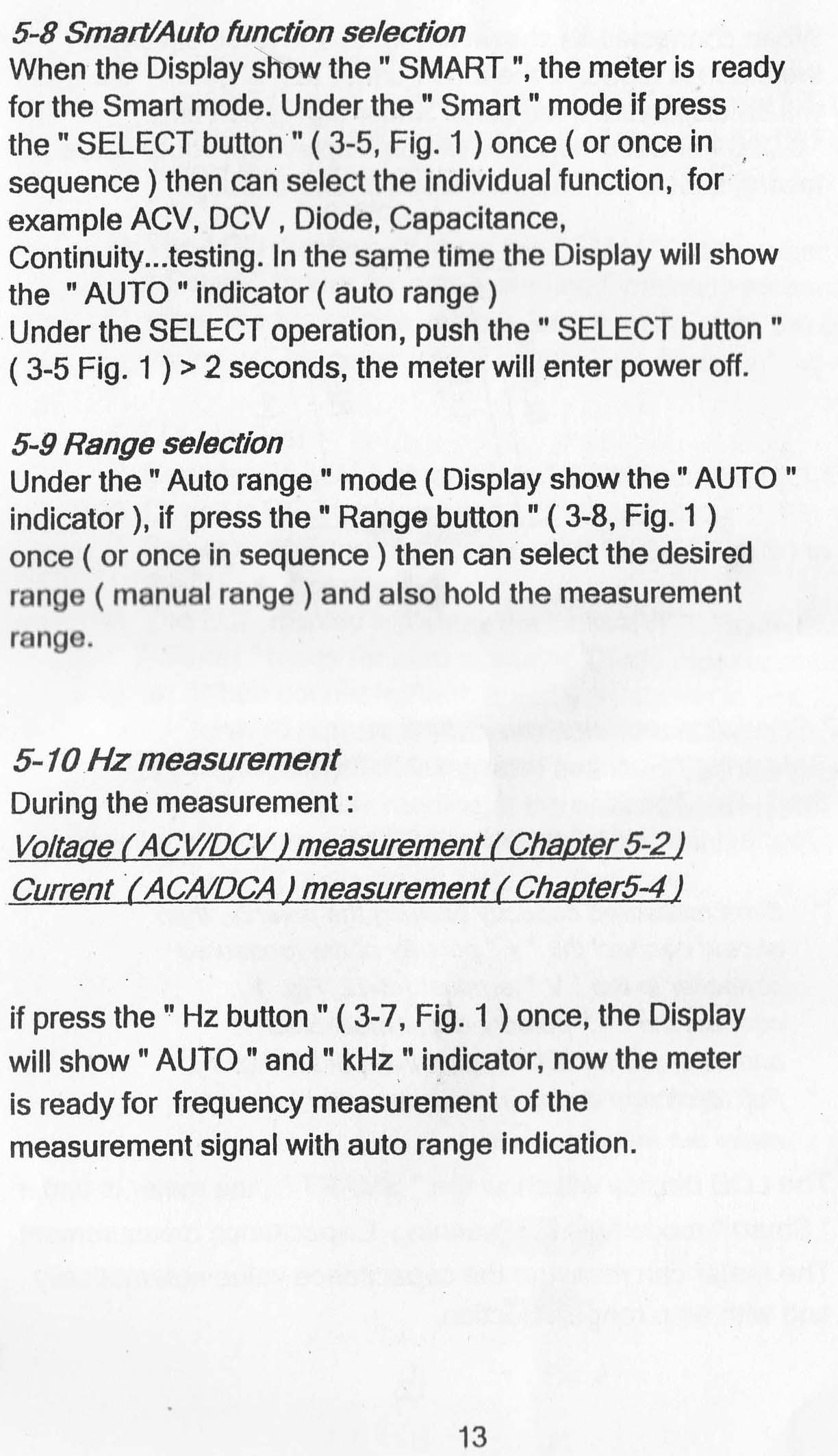
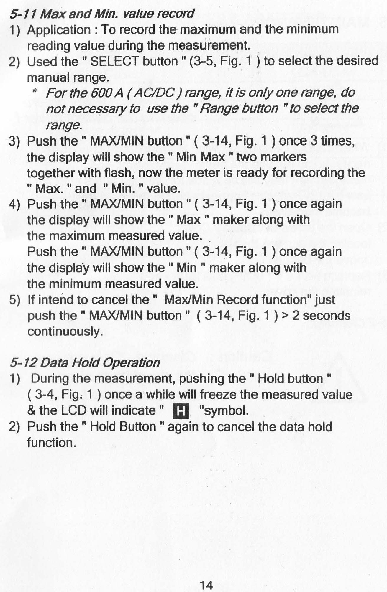
Function keys : Select, Zero, Hz, Max/Min, Range, Hold.
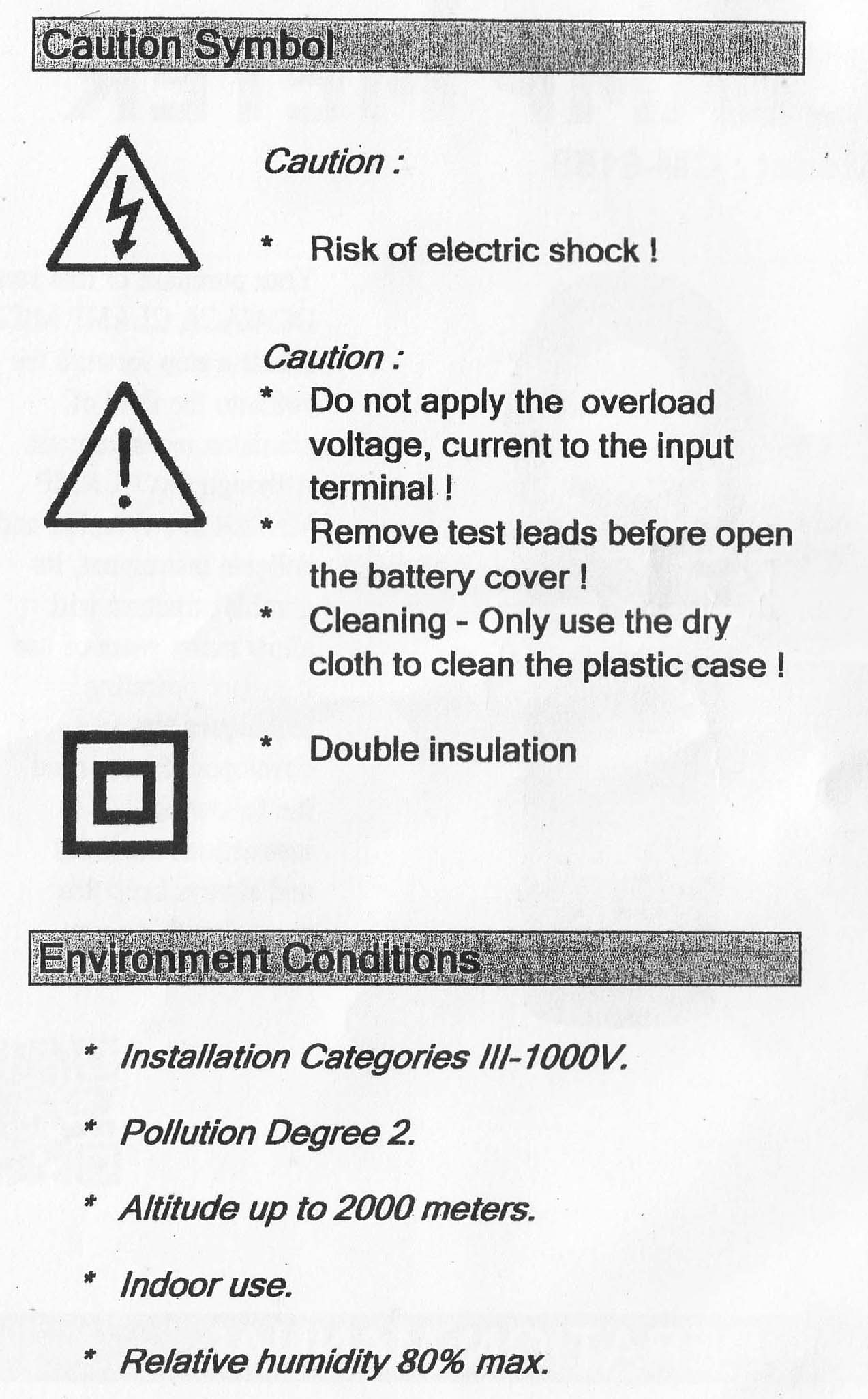
CAT III 1000V, CAT IV 600V.
Max. hold (Max., Min. measuring value).
48 mm measuring conductor size.
Auto power off.
Penampakan
Berikut ini penampakan alat ukur clamp meter tersebut.
Alat ukur CM-6158
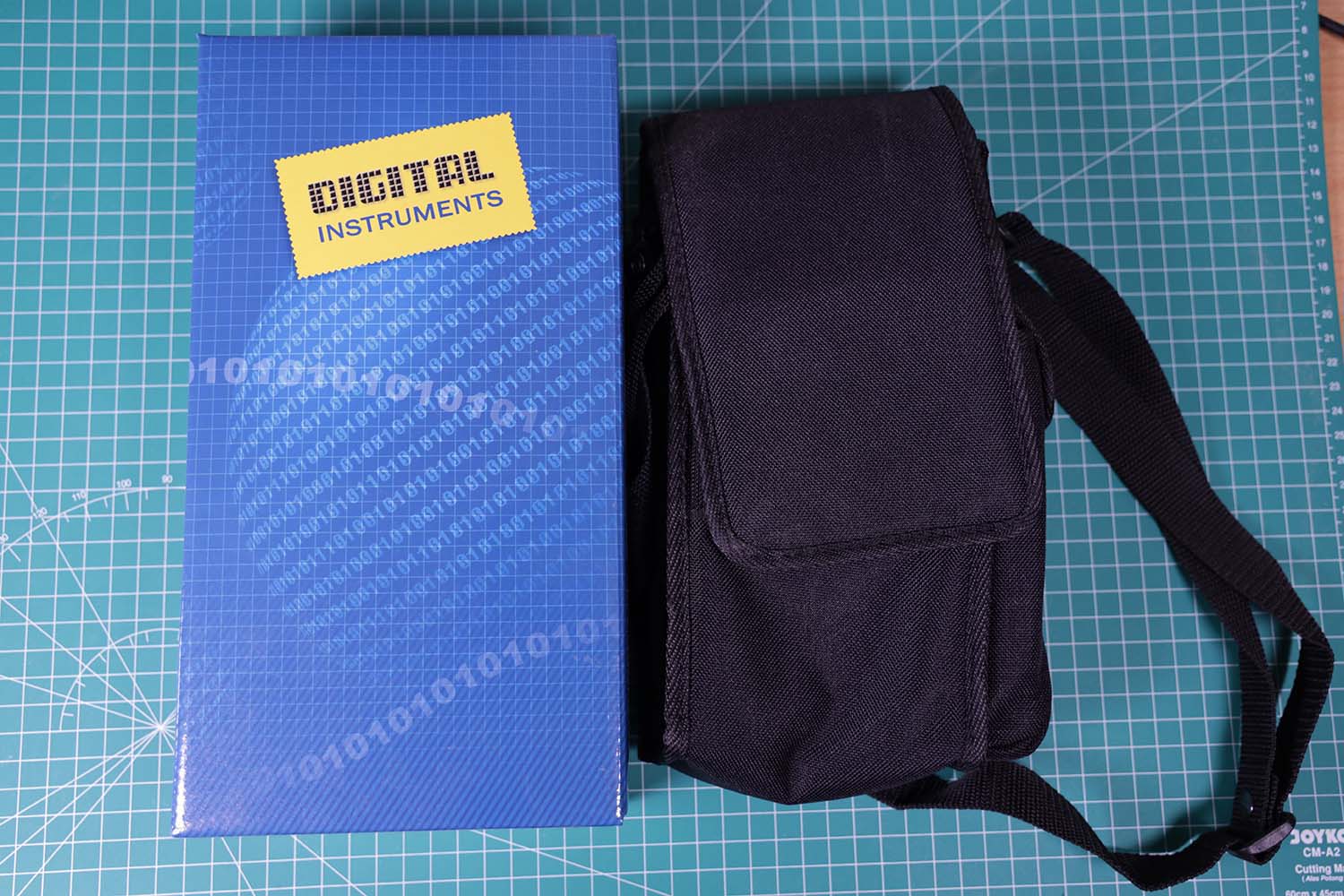
Kemasan alat ini menggunakan kardus warna biru. Warna dan desainnya sama seperti produk Lutron lainnya seperti anemometer dan light meter. Tas kecil juga disediakan. Tas ini dapat diisi alat ukur dan probe sensornya.
Kotak dan wadah
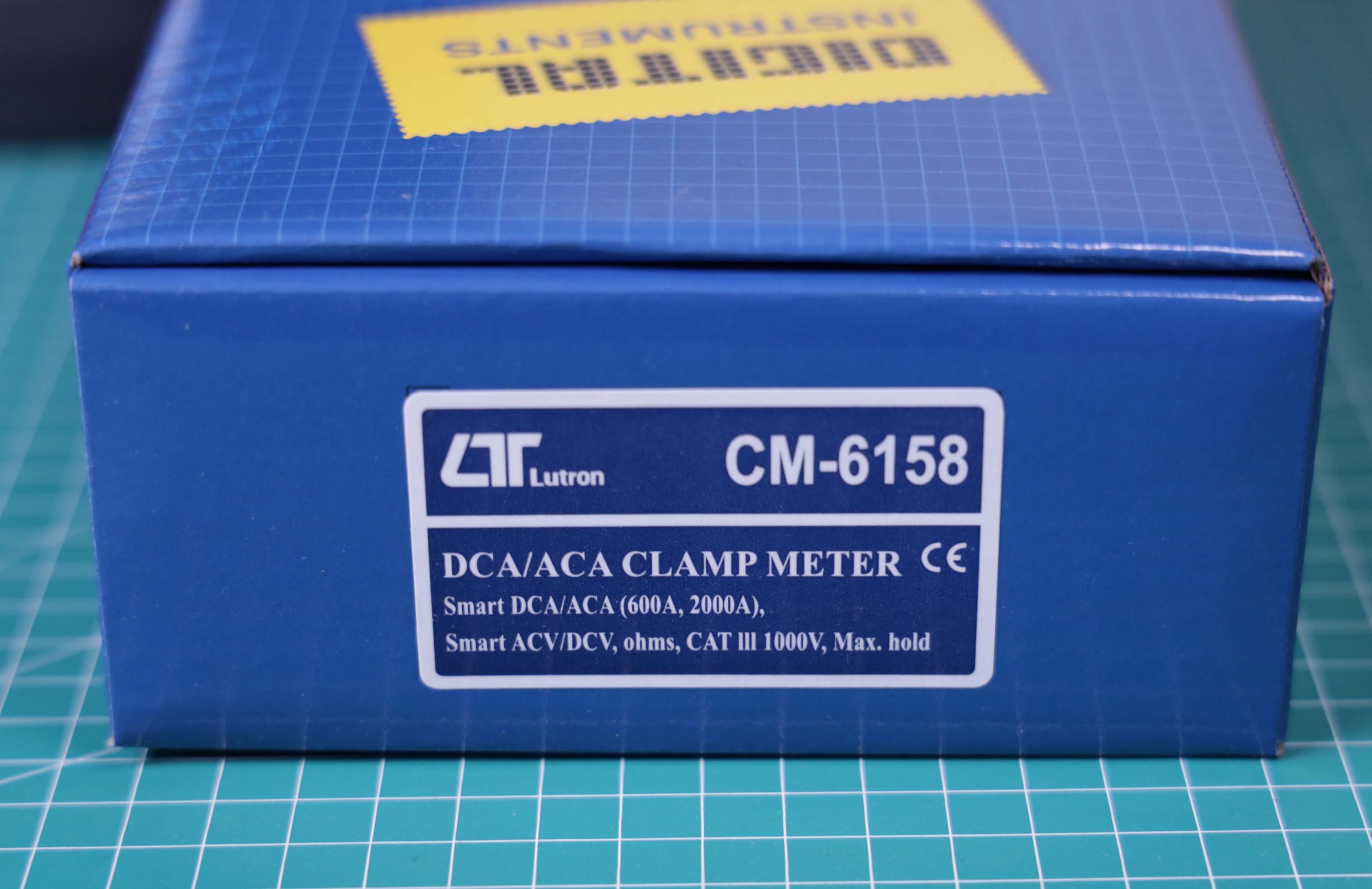
Pada kotak tertera spesifikasi ringkas alat ukur ini, yaitu pengukuran arus DC dan AC sampai 600 ampere dan 2000 ampere, serta tegangan AC & DC, serta resistansi (ohm).
Kotak CM-6158
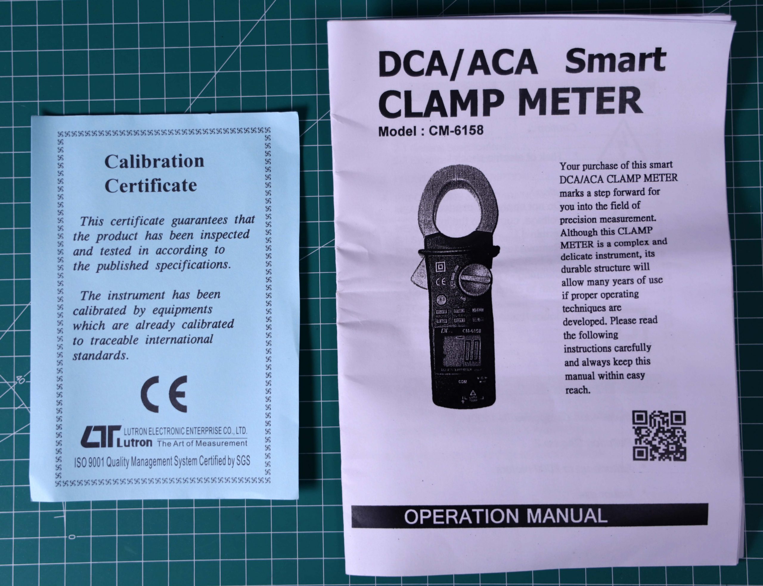
Dokumen yang disertakan adalah sertifikasi kalibrasi dan manual. Manual diberikan dalam bentuk hardcopy fotokopian. Manual ini menurut saya sangat minimalis, namun cukup dimengerti. Manual online tidak ditemukan.
Manual dan sertifikasi kalibrasi
Review CM-6158
Clamp meter ini cukup berat, dibandingkan dengan multimeter biasa
Alat ini cukup besar. Bagi saya mudah memegangnya karena tangan saya besar.
Penggunaan sangat mudah
Dapat mengukur arus DC dengan baik. Bagi yang biasa pakai multimeter, perlu membiasakan dengan melakukan “DCA Zero” sebelum melakukan pengukuran arus
Bentuknya bagus, tekstur materialnya bagus enak dipegang
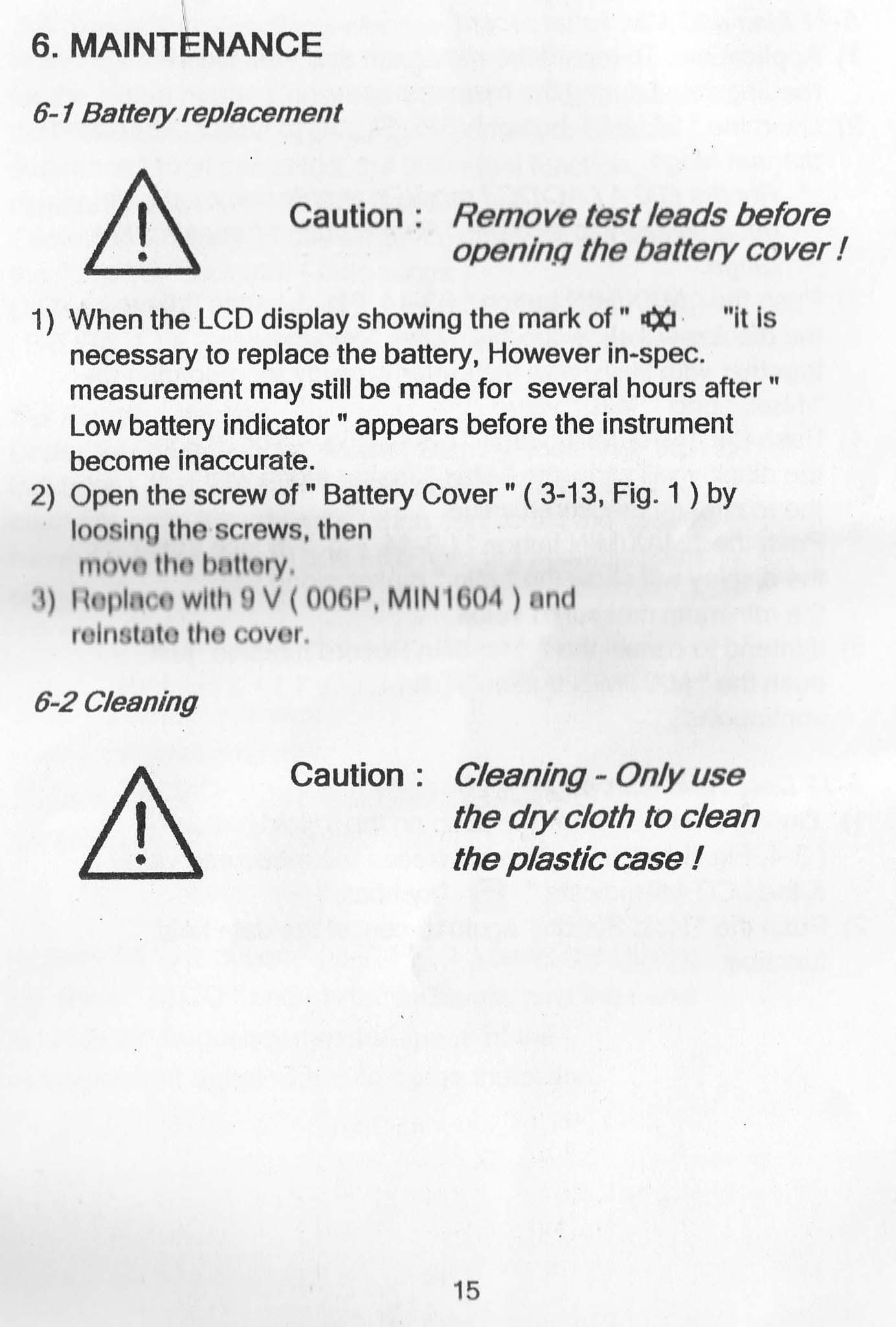
Pada waktu pembelian sudah dilengkapi dengan baterai 9 volt, jadi tinggal pasang
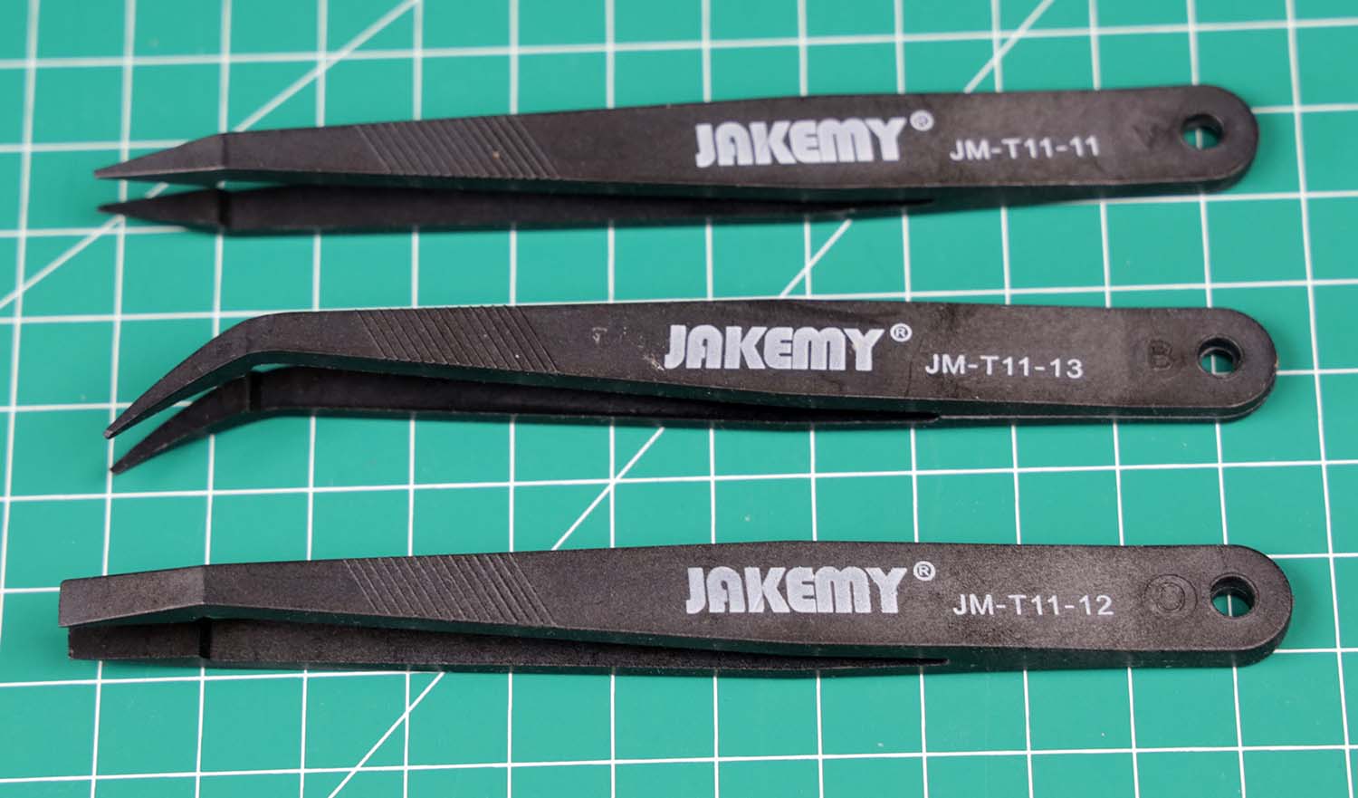
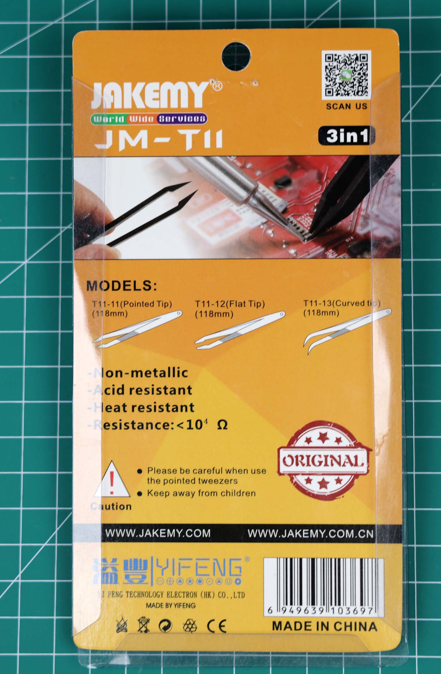
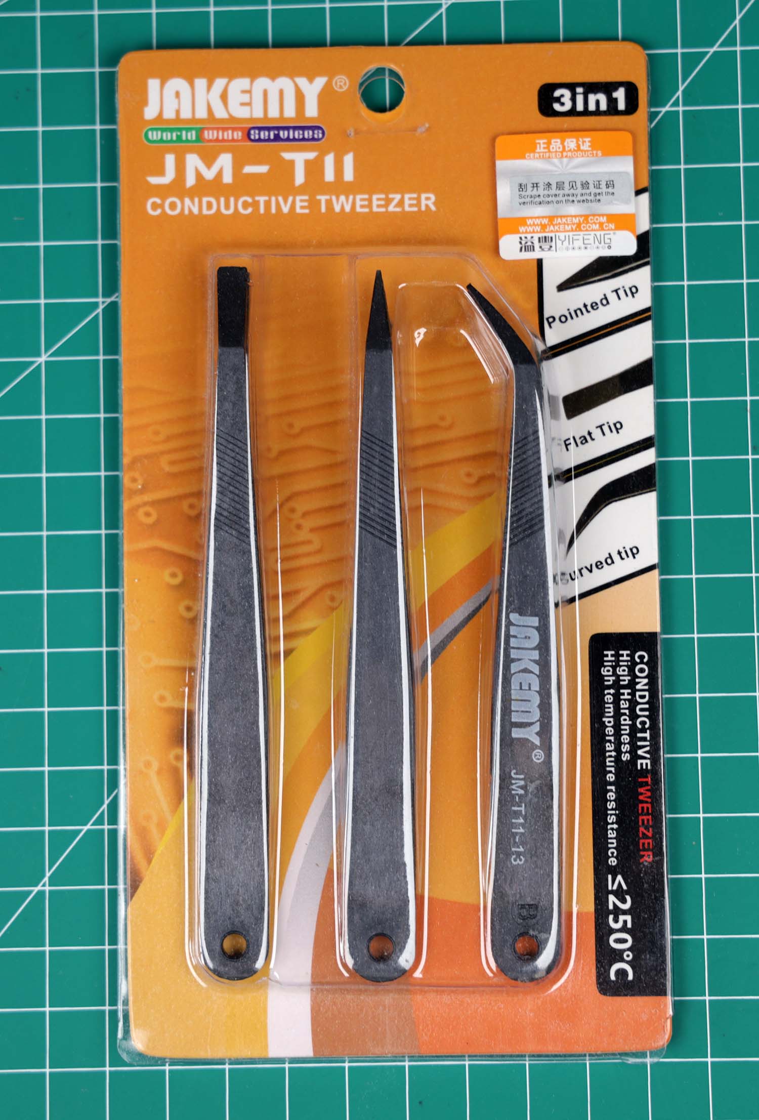
Pinset ini sangat berguna untuk menangani komponen-komponen elektronika yang berukuran sangat kecil.
Pinset ini terbuat dari bahan konduktif dengan resistansi cukup tinggi. Hal ini membantu mengatasi masalah listrik statis. Listrik statis tidak akan menumpuk pada pinset ini , karena bahannya konduktif. Selain itu, muatan listrik dari badan kita juga tidak akan mengalir dengan mudah, karena pinset ini memiliki resistansi cukup tinggi, sehingga arus pembuangan (discharge) listrik statis relatif kecil.
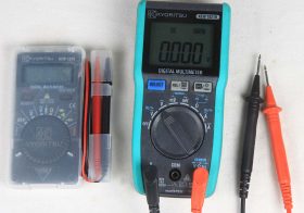
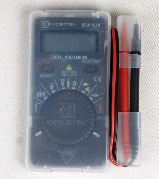
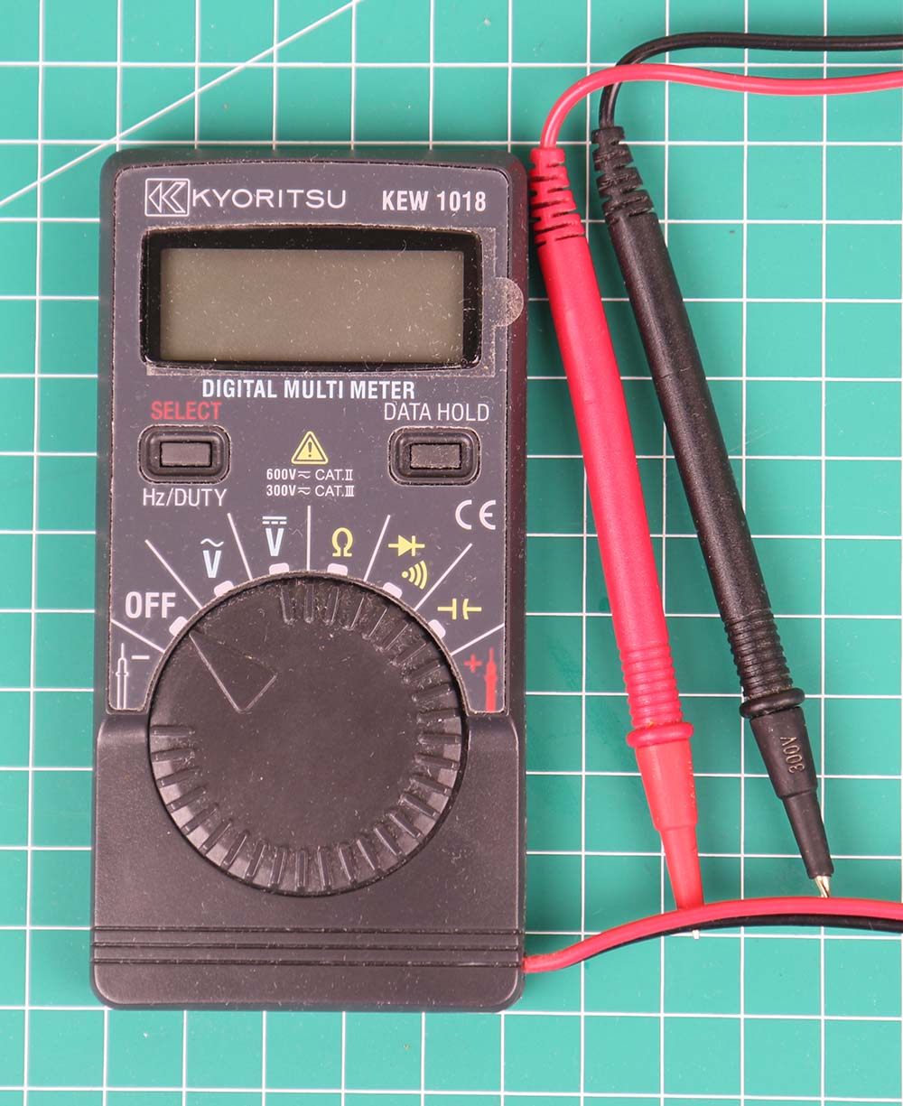
Kyoritsu KEW1018, multimeter kecil dengan kemampuan tinggi.
Kyoritsu KEW 1018
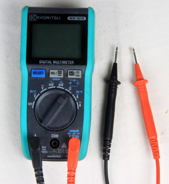
Kyoritsu KEW1021, multimeter dengan ukuran standar.
Kyoritsu KEW 1021R
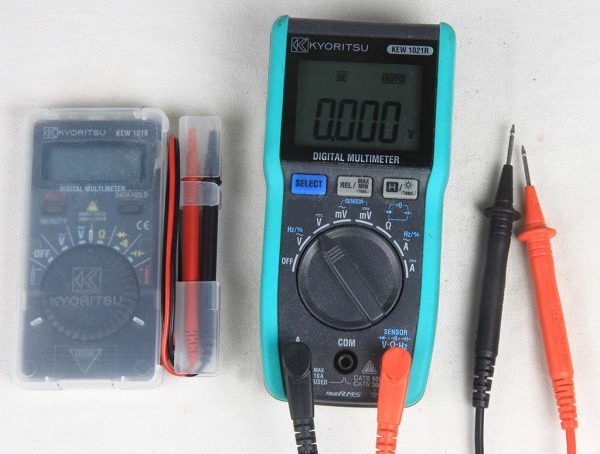
Perbandingan ukuran antara KEW1018 dan KEW1021R. KEW1021 juga dilengkapi backlight berwarna oranye.
Kyoritsu KEW 1018 dan KEW 1021R
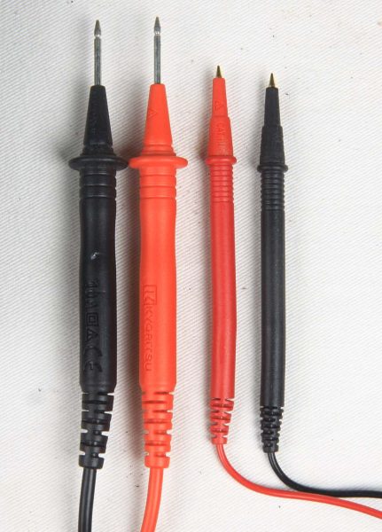
Berikut perbandingan ukuran probe. KEW1018 probenya sangat mungil.
Probe Kyoritsu KEW 1018 dan KEW 1021R
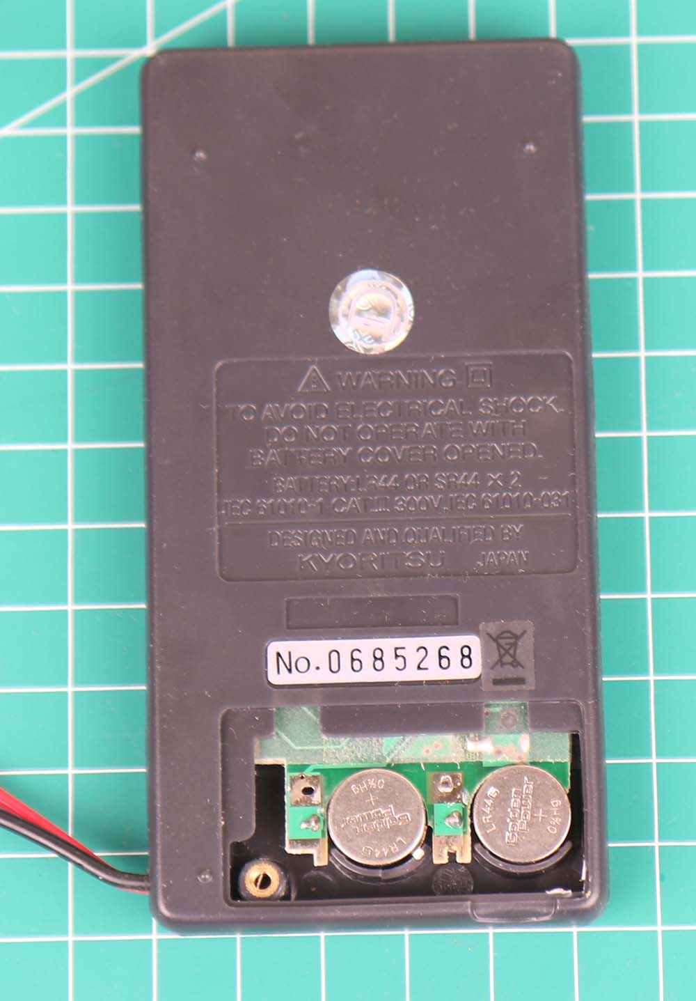
Berikut ini penampakan Kyoritsu KEW-1018 tanpa casing plastiknya.
Kyoritsu KEW 1018 tampak belakang
Nampak kecil sekali. 1 kotak di gambar berukuran 1 cm x 1 cm. Baterai menggunakan 2 buah baterai kancing lithium tipe SR-44
Kyoritsu KEW 1018 tampak depan
Kelebihan utama KEW 1021R dibandingkan KEW1018
Ada fitur pengukuran kapasitansi
ada fitur pengukuran arus listrik
Dimensi lebih besar, lebih enak di tangan terutama bagi yang bertangan besar. KEW1018 mungkin enak dipakai bagi anak-anak yang sedang belajar elektronika.
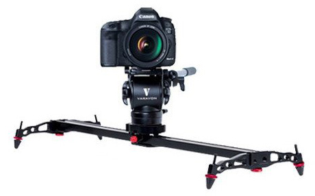
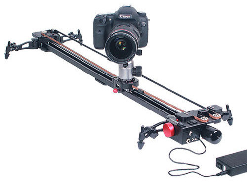
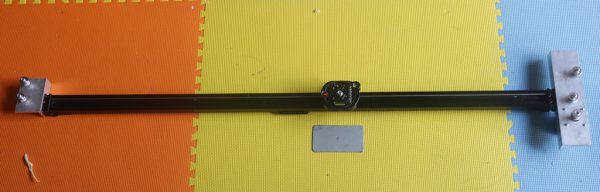
Slidecam Lite 1000 adalah slider buatan Varavon sepanjang 1 meter.
Varavon Lite 1000
Slider ini dapat digerakkan secara manual dengan menggesernya dengan tangan. Untuk beberapa aplikasi seperti time lapse, lebih nyaman kalau kita menggunakan penggerak motor yang dapat menggerakkan slider ini secara otomatis.
Varavon mengeluarkan produk motor untuk slider ini yaitu Motorroid Slider Motorized Kit. Namun demikian harga kit motor ini lumayan mahal, 4x harga slidernya sendiri. Untuk itu akan dicoba membuat penggerak motor sendiri untuk slider tersebut.
Varavon Motorroid L1000
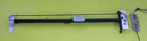
Berikut ini foto penggerak slider
Motorized Slider
Perangkat penggerak dibagi menjadi 2 bagian:
Bagian mekanikal : meliputi motor, belt, pulley serta dudukannya
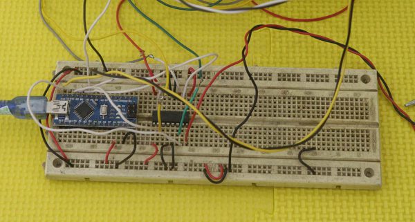
Bagian elektrikal: mikrokontroler Arduino , penggerak motor dan user interface.
Bagian mekanikal dibagi 3:
Dudukan motor : berisi dudukan motor di salah satu ujung
Dudukan tanpa motor: berisi dudukan pulley di ujung yang lain
Dudukan kamera dan belt: di bagian kereta yang berisi kamera
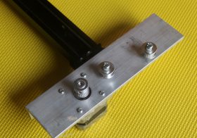
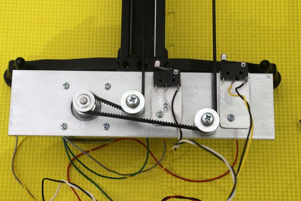
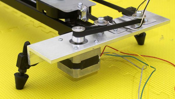
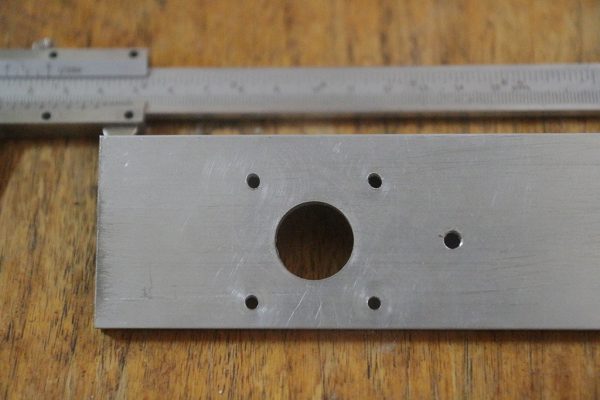
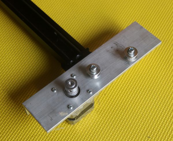
Berikut ini detail dari bagian dudukan motor
Tampak atas dudukan motor
Tampak samping dudukan motor
Tampak samping dudukan motor dengan motor stepper
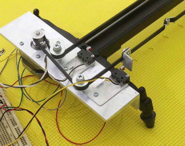
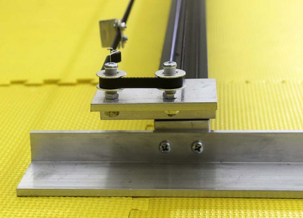
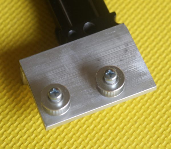
Bagian selanjutnya adalah dudukan pulley tanpa motor
Dudukan pulley tanpa motor
Dudukan pulley tanpa motor
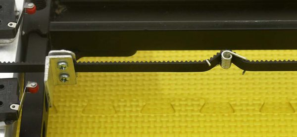
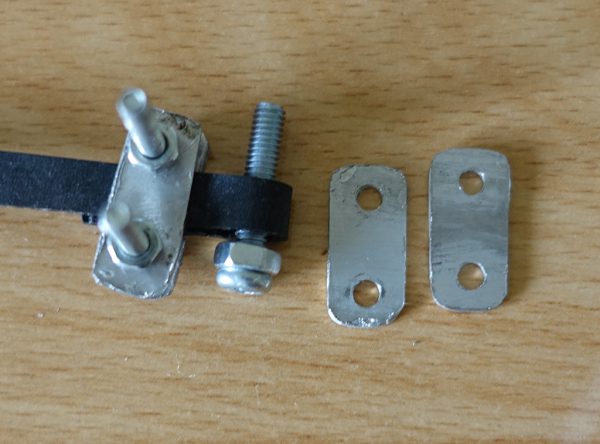
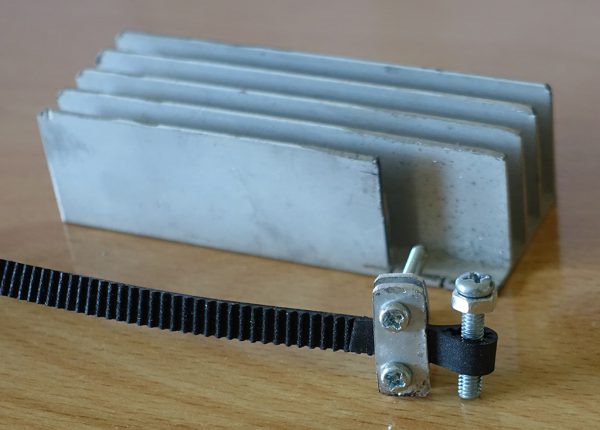
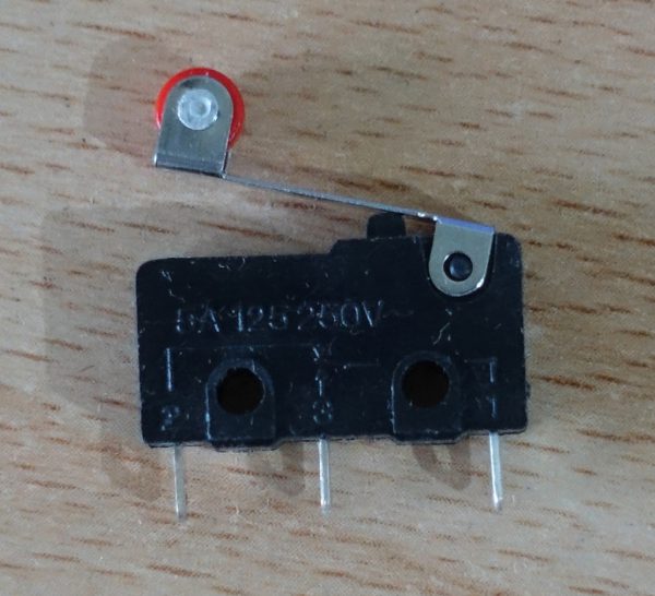
Berikutnya adalah belt tipe 2GT. Pada belt ini dipasang kepingan aluminium untuk trigger microswitch, sehingga mikrokontroler Arduino dapat menghentikan motor jika kamera sudah sampai di salah satu ujung.
Pada belt juga dipasang tensioner untuk menjaga agar belt tetap kencang, tidak kendor.
Belt dan tensioner untuk belt
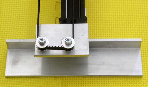
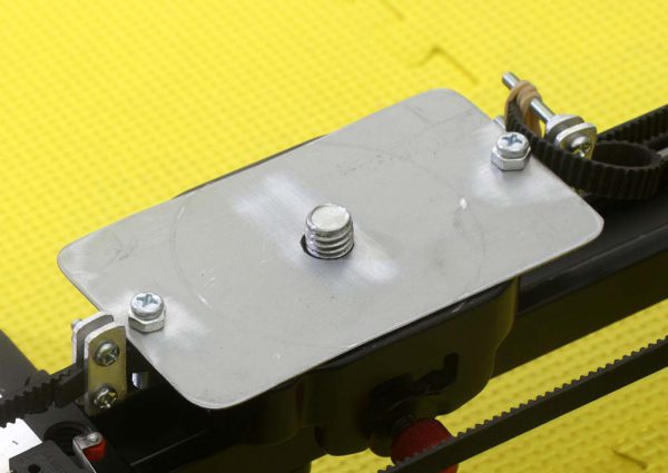
Kepingan logam tipis dipakai sebagai sangkutan belt ke dudukan kamera. Ide menggunakan kepingan logam ini meniru dari Motorized Varavon.
Dudukan kamera
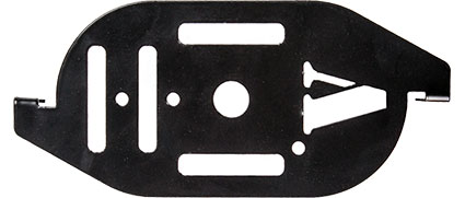
Berikut ini saddle asli buatan Varavon. Nampaknya dibuat dari stainless steel yang dipunch dan ditekuk. Bagian-bagiannya dibuat berlubang agar ringan. Berhubung sulit untuk dicopy paste 100%, akhirnya dibuat saja modifikasinya.
Komponen tambahan yang diperlukan adalah L293D sebagai penguat arus untuk motor stepper. Power supply menggunakan 5 volt dari USB dan 12 volt dari power supply terpisah.
Pengendali Arduino Nano
Proses Pembuatan
Berikut ini beberapa foto proses pembuatan motorized slider ini.
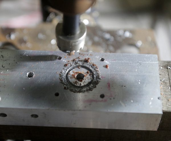
Proses pengeboran dengan holesaw 20 mm
Lubang untuk motor stepper NEMA 17 selesai
Dudukan Motor
Pembuatan Dudukan Tanpa Motor
Dudukan tanpa motor
Proses pembuatan dudukan kamera dan belt
Komponen yang dipakai adalah aluminium tipis dari heatsink bekas, mur baut 3 mm dan mur baut 4 mm.
Sangkutan belt
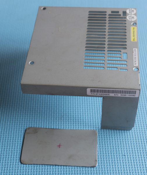
Dudukan kamera dibuat dari besi bekas casing power supply.
Casing power supply
Slider dan plat besi
Komponen
Berikut ini beberapa komponen yang dipakai untuk pembuatan penggerak slider ini:
Berikut ini beberapa perangkat yang dipakai untuk pembuatan penggerak slider ini:
Bor duduk
Mata bor 5 mm
Mata bor 3 mm
Tap drill 5 mm
Tap drill 3 mm
Mata bor holesaw 20 mm
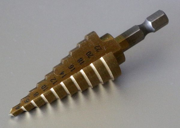
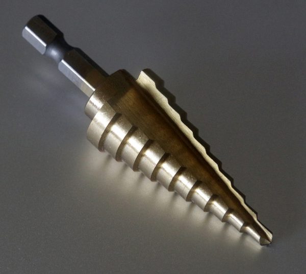
Step drill 4 mm ~ 22 mm
Step Drill
Step drill dipakai untuk membuat lubang untuk motor stepper. Pertama-tama menggunakan bor holesaw 20mm, kemudian lubang diperlebar sampai 22 mm dengan step drill ini. Setelah itu masih perlu digerinda dengan Dremel supaya casing motor stepper yang berukuran 22 mm dapat masuk ke lubang tersebut.
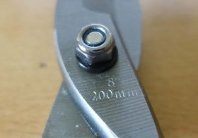
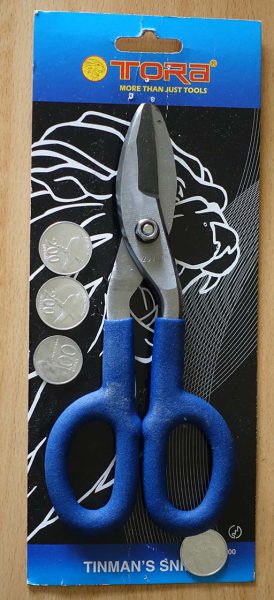
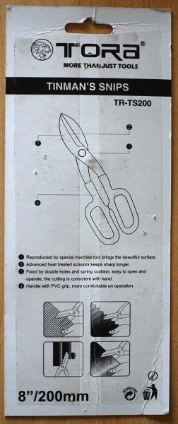
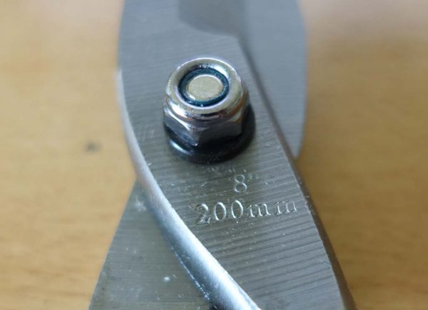
Gunting Besi atau Tinman Snips, berguna untuk memotong logam tipis. Berikut ini foto-foto gunting besi / tinman snips tipe Tora TR-TS200. Panjangnya 20 cm / 8″. Finishingnya presisi, mulus dipakai untuk memotong. Penggunaan seharusnya adalah untuk memotong logam tipis, namun dicoba untuk memotong kertas maupun plastik tipis juga tidak masalah. Gagangnya menggunakan bahan PVC biru yang empuk dan tidak licin, sangat nyaman.
Penampakan gunting besi Tora TR-TS200
Keterangan di belakang kemasan Tora TR-TS200
Bagian poros menggunakan mur yang dapat diatur kekencangannya. Selain itu juga dilengkapi dengan pegas, sehingga kedua bilah gunting selalu menempel dengan rapat.
Poros dengan sekrup dan per
Jika oprekan kita melibatkan metal tipis, gunting besi ini sangat berguna.
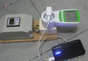
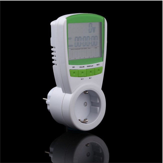
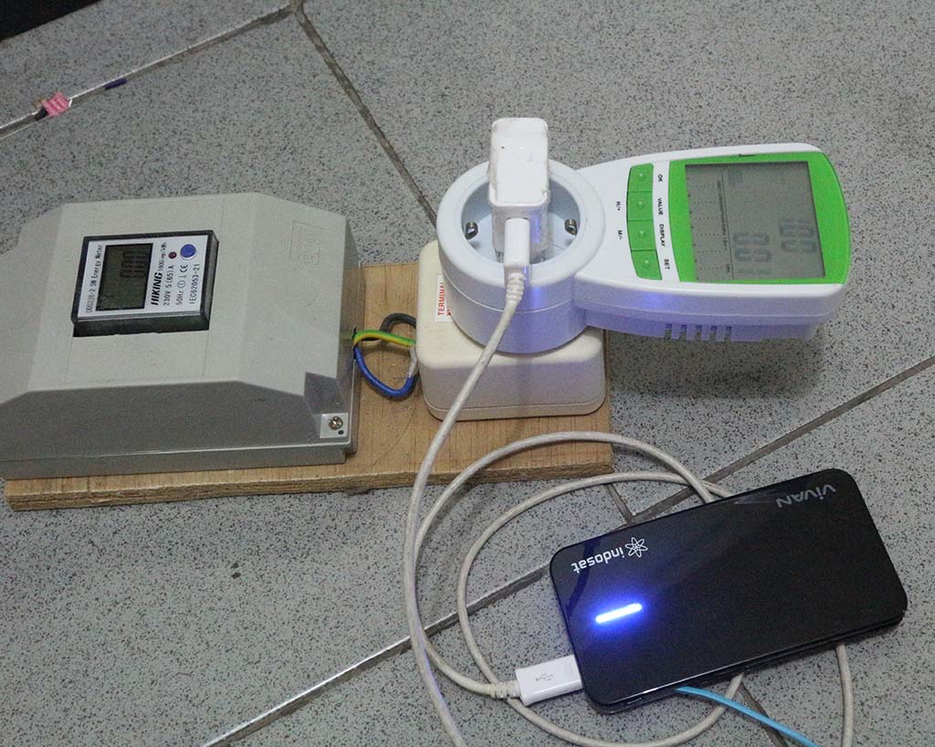
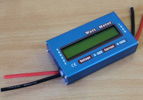
Energy Meter TS-838 ini mempunyai kemampuan mengukur pemakaian daya listrik. Fungsinya seperti kWh meter, namun lebih lengkap karena ada juga pengukuran tegangan, arus dan faktor daya. Selain itu tampilannya digital sehingga cukup memikat.
Features:
Measures various parameters: power (W), energy (kWh), volts, amps, hertz, power factor and maximum power (W), time, days – kWh is vital as this is what your electricity bills are based on!
Overload Protection Function, overload warning
Large, clear LCD display for easy reading (screen dimension: 50mm x 43mm)
Cumulative Kilowatt-Hour Monitor
Calculates electricity expenses
Electricity price setting by pressing SET, VALUE, DISPLAY
Can also set energy Price for night separately
Sets electricity price value which ranges 0.000COST/KWH ~9.999COST/KWH
Low power consumption
Power supply: 2*1.5V Button cell backup – allows meter to be moved (and viewed) without losing readings. NO Backlight
Specifications
Overload Protection Function: When the whole power exceeds the rated power of monitor, the monitor will cut off the current and prevent being damaged
Operating voltage: 120VAC
Frequency display: 50/60HZ
Operating current: max 15A
Voltage range: 110V-130V
Wattage display (Watts) is 0~1800W
-Current range: 0.01A~19.99A
Resolution: 0.5W
Indication of frequency: 46-65HZ
Measurement of consumption: 0.00 to 9999.99 KWh
Duration of indication: up to 9,999 hours 59 minutes
Berikut ini beberapa penampakan energy meter TS-838.
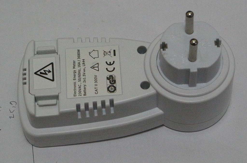
Berikut ini adalah bagian bawah dari energy meter TS-838. Pada body perangkat ini sama sekali tidak ada tulisan model ataupun merek. Nampaknya ini barang generik, yang dapat disablon ke merek lain.
Penampakan bagian bawah
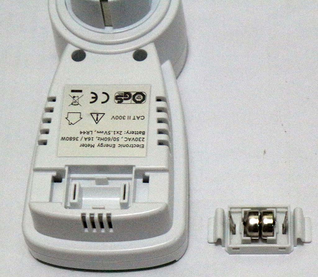
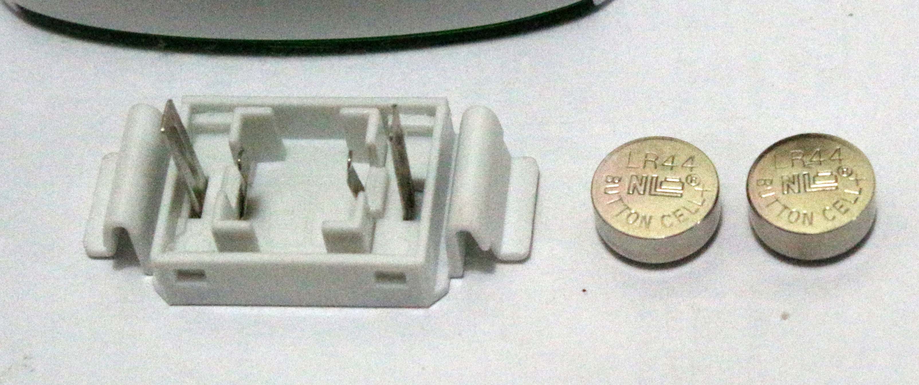
Penyimpanan data di dalamnya menggunakan 2 buah batere LR44, supaya rekaman data pemakaian daya tidak hilang ketika listrik mati.
Energy meter TS-838 dengan batere backup
Batere backup 2 buah LR44
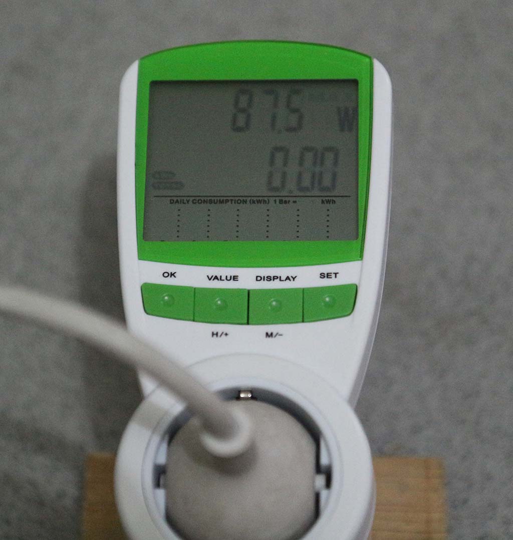
Berikut ini adalah tampilan pemakaian daya (87.5 watt).
Energy meter TS-838 sedang menampilkan daya
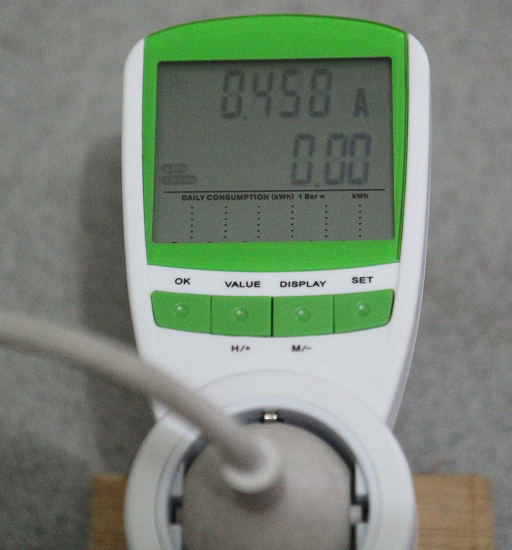
Berikut ini tampilan pengukuran arus (0.45 ampere)
Energy meter TS-838 sedang mengukur arus
Manual
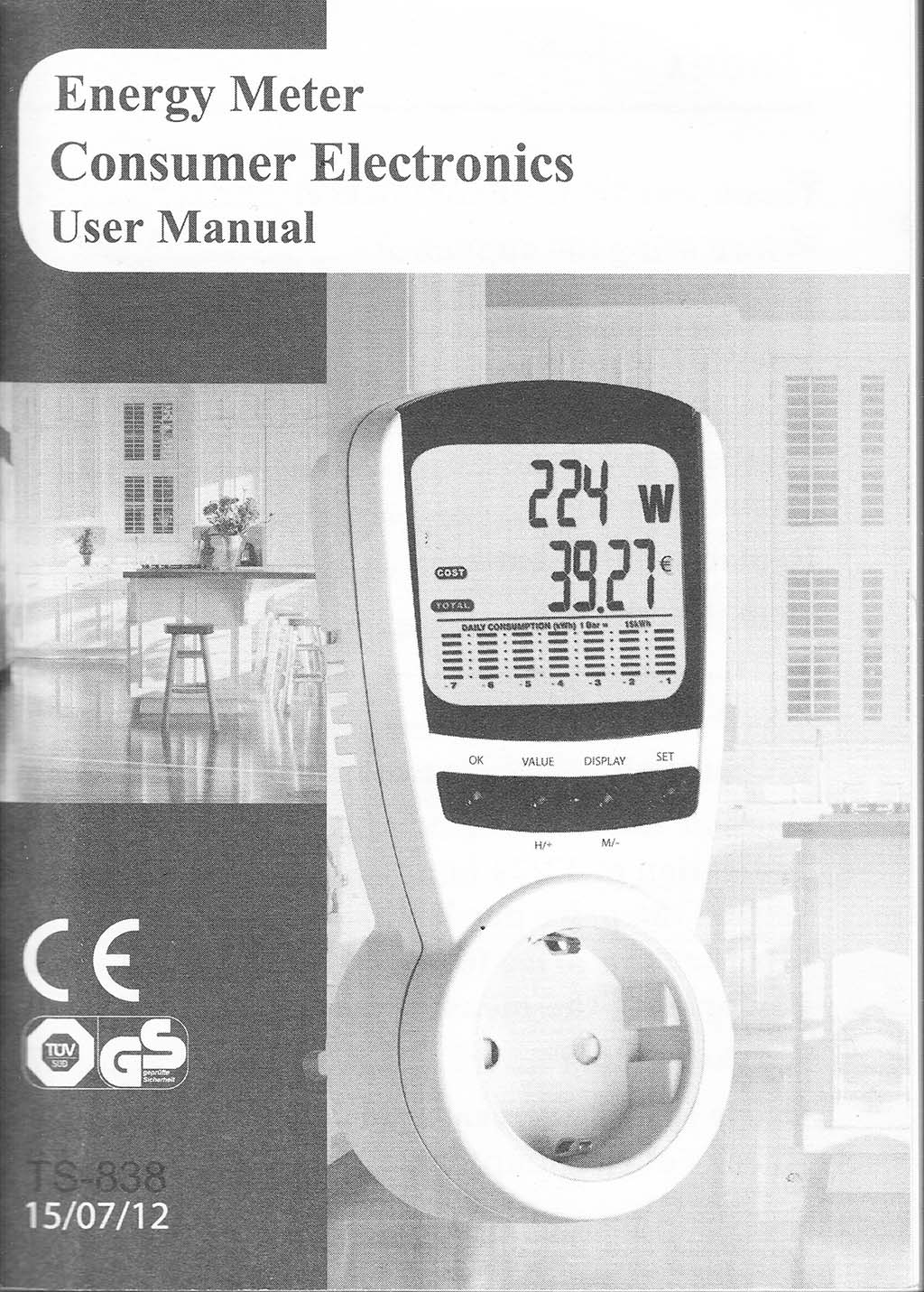
Berikut ini manual dari TS-838
Manual halaman 1
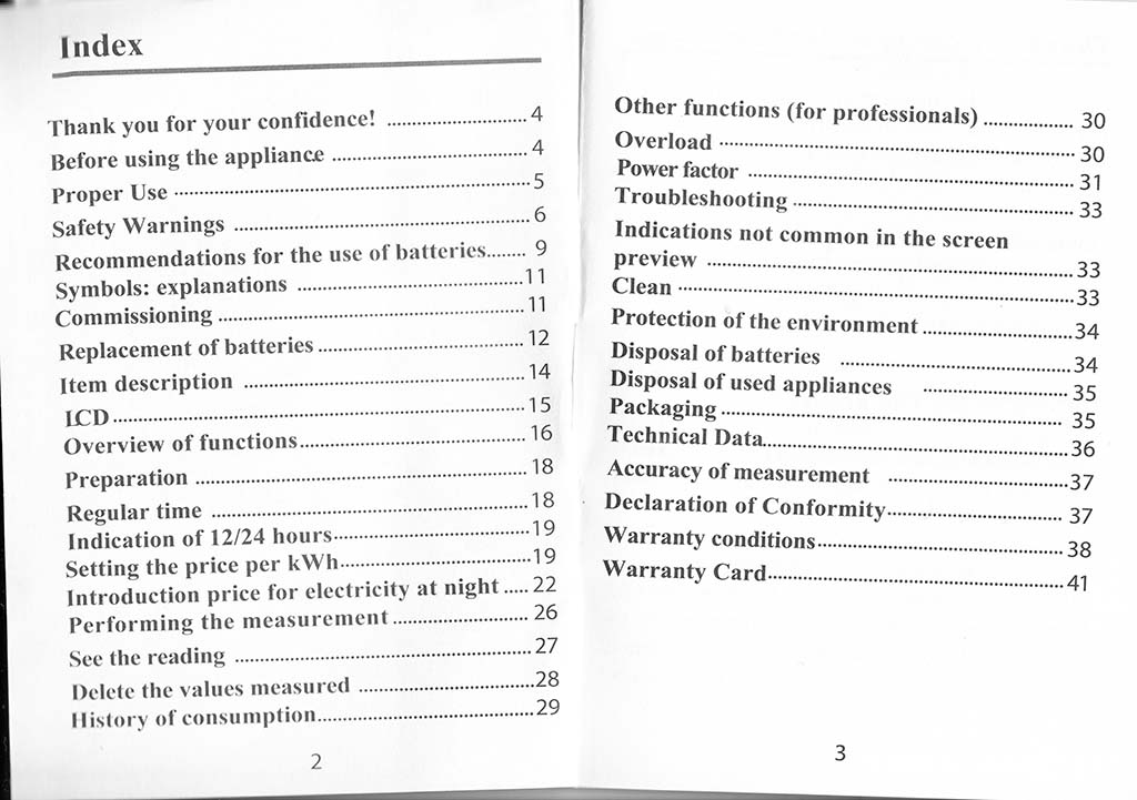
Manual halaman 2
Manual halaman 4
Manual halaman 6
Manual halaman 8
Manual halaman 10
Manual halaman 12
Manual halaman 14
Manual halaman 16
Manual halaman 18
Manual halaman 20
Manual halaman 22
Manual halaman 24
Manual halaman 26
Manual halaman 28
Manual halaman 30
Manual halaman 32
Manual halaman 34
Manual halaman 36
Manual halaman 38
Manual halaman 40
Teks Manual
Energy Meter
Consumer Electronics User Manual
Index
Thank you for your confidence! …………4
Before using the appliance________________ 4
Proper Use——————————– 5
Safety Warnings……………………… 6
Recommendations for the use of batteries..9
Symbols: explanations…………………11
Commissioning………………………..11
Replacement of batteries………………12
Item description —…………………… 14
ICD…………………………………15
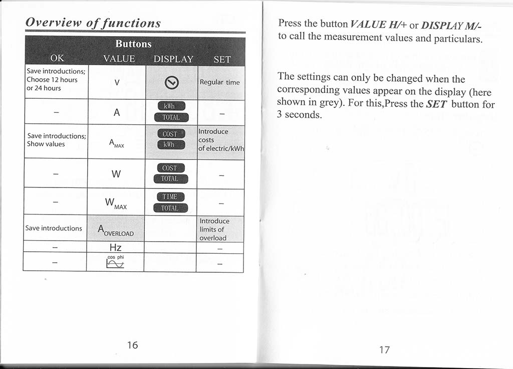
Overview of functions——————— 16
Preparation ………. ……….. -………….. 18
Regular time…………………………16
Indication of 12/24 hours……………..19
Setting the price per kWh……………..19
Introduction price for electricity at night.22
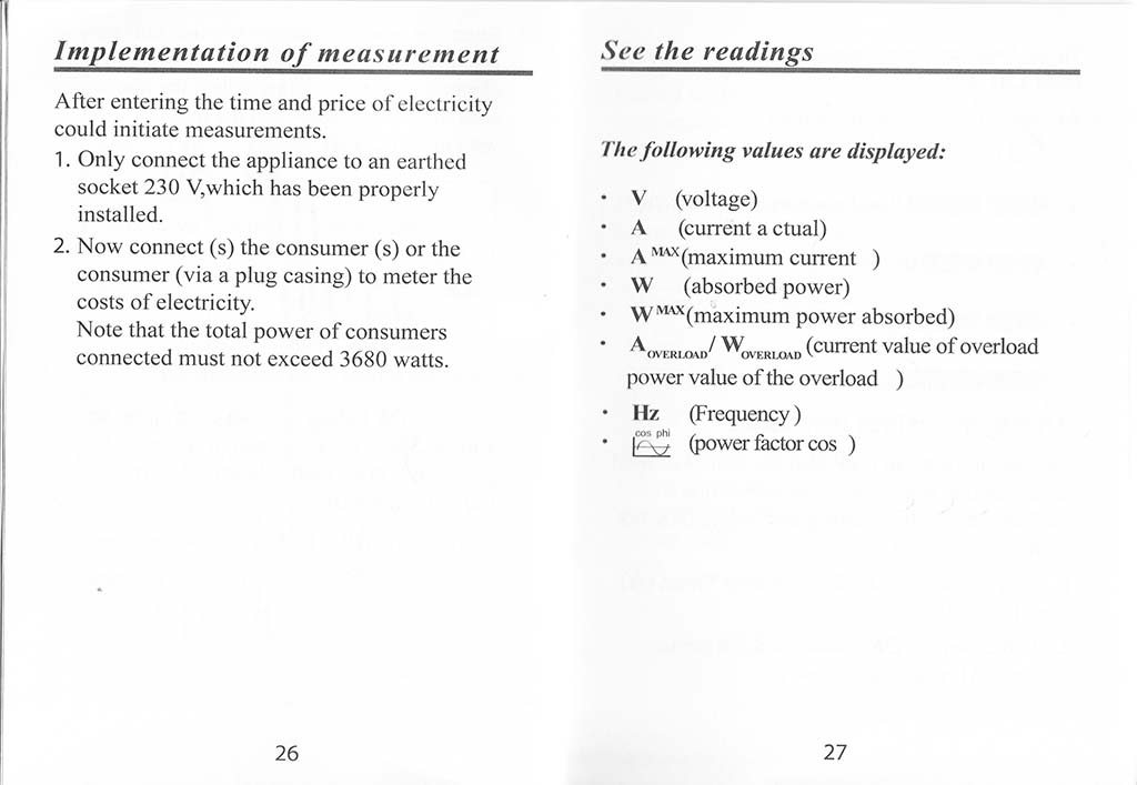
Performing the measurement…………….26
See the reading………………………27
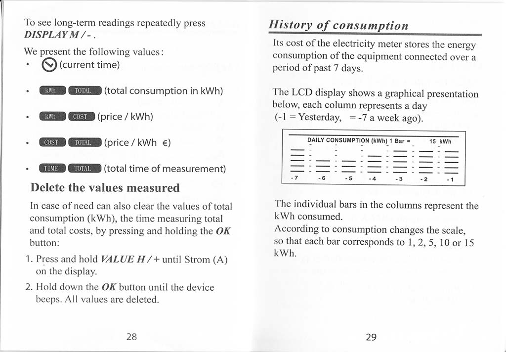
Delete the values measured…………….28
History of consumption……………… 29
2
Other functions (for professionals)……….30
Overload……………………………….30
Power factor …———————…………….. 31
Troubleshooting…………………………33
Indications not common in the screen preview -—….—……—.—.—…………—………… 33
Clean…………………………..*…….33
Protection of the environment…………….34
Disposal of batteries ___________________…….. 34
Disposal of used appliances ……………..35
Packaging————————————35
Technical Data_______________________________36
Accuracy of measurement …………………37
Declaration of Conformity………………..37
Warranty conditions————————–38
Warranty Card…………………………..41
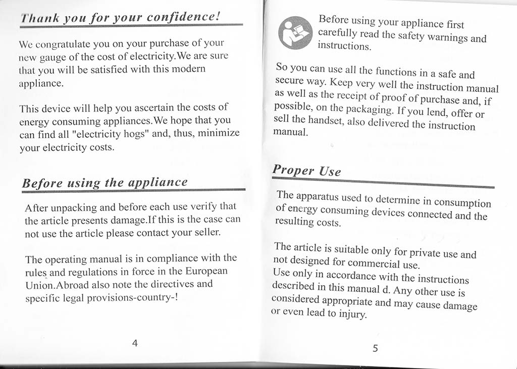
Thank you for your confidence!
We congratulate you on your purchase of your new gauge of the cost of electricity. We are sure that you will be satisfied with this modern appliance.
This device will help you ascertain the costs of energy consuming appliances. We hope that you can find all “electricity hogs” and, thus, minimize your electricity costs.
Before using the appliance
After unpacking and before each use verify that the article presents damage.If this is the case can not use the article please contact your seller.
The operating manual is in compliance with the rules and regulations in force in the European Union.Abroad also note the directives and specific legal provisions-country-!
Before using your appliance first carefully read the safety warnings and instructions.
So you can use all the functions in a safe and secure way. Keep very well the instruction manual as well as the receipt of proof of purchase and, if possible, on the packaging. If you lend, offer or sell the handset, also delivered the instruction manual.
Proper Use
The apparatus used to determine in consumption of energy consuming devices connected and the resulting costs.
The article is suitable only for private use and not designed for commercial use.
Use only in accordance with the instructions described in this manual d. Any other use is considered appropriate and may cause damage or even lead to injury.
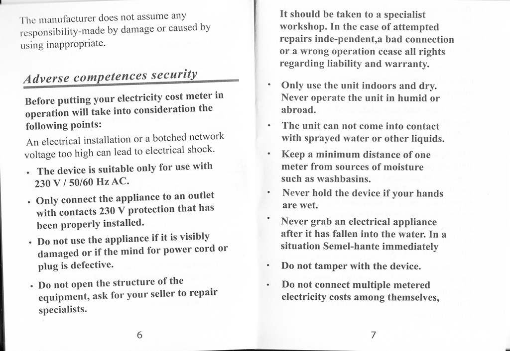
The manufacturer does not assume any responsibility-made by damage or caused by using inappropriate.
Adverse competences security
Before putting your electricity cost meter in operation will take into consideration the following points:
An electrical installation or a botched network voltage too high can lead to electrical shock.
• The device is suitable only for use with 230 V / 50/60 Hz AC.
• Only connect the appliance to an outlet with contacts 230 V protection that has been properly installed.
• Do not use the appliance if it is visibly damaged or if the mind for power cord or plug is defective.
• Do not open the structure of the equipment, ask for your seller to repair specialists.
It should be taken to a specialist workshop. In the case of attempted repairs inde-pendent,a bad connection or a wrong operation cease ail rights regarding liability and warranty.
Only use the unit indoors and dry. Never operate the unit in humid or abroad.
The unit can not come into contact with sprayed water or other liquids. Keep a minimum distance of one meter from sources of moisture such as washbasins.
Never hold the device if your hands are wet.
Never grab an electrical appliance after it has fallen into the water. In a situation Semel-hante immediately
Do not tamper with the device.
Do not connect multiple metered electricity costs among themselves,
Do not cover the appliance with other materials by exists the danger of overheating.
When not using the device or if a malfunction occurs, disconnect the power source.
Dangers for children!
Often children do not recognize or underestimate the dangers.
Keep bags and materials used to pack the machine away from babies and small children. Danger of suffocation!
This appliance is not suitable for use by persons (including children) with a capacity of physical, sensory or intellectual abilities, or who does not experience and / or sufficient knowledge, unless they are under the supervision of a person that is responsible for their safety or that have had instructions on how to operate the device.
Supervise children and keep the appliance out of their reach to ensure that they do not play with the appliance. The their misuse means danger of electric shock!
Recommendations for the use of batteries
The meter cost of electricity in the functional with 2 batteries (button) of the type LR44 or AG 13 (these batteries are included).
Only use the battery type here specified, in order to prevent fire. Never attempt to charge the batteries.
Do not throw batteries into a fire, not short-circuit the batteries or try to take them apart! Danger of explosion!!
Keep batteries out of reach of children.
Seek immediate medical attention if swallowing a battery.
Immediately remove the batteries inside the device! Heightened risk of leakage!
Those cells not exposed to extreme conditions, such as heaters over! As in radiators or in direct sunlight! Heightened risk of leakage!
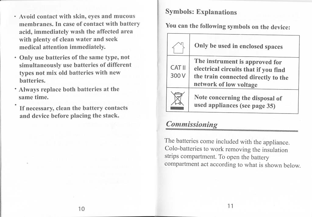
Avoid contact with skin, eyes and mucous membranes. In case of contact with battery acid, immediately wash the affected area with plenty of clean water and seek medical attention immediately.
Only use batteries of the same type, not simultaneously use batteries of different types not mix old batteries with new batteries.
Always replace both batteries at the same time.
If necessary, clean the battery contacts and device before placing the stack.
Symbols: Explanations
You can the following symbols on the device:
Only be used in enclosed spaces
CAT II 300 V The instrument is approved for electrical circuits that if you find the train connected directly to the network of low voltage
| Note concerning the disposal of used appliances (see page 35)
Commissioning
The batteries come included with the appliance. Colo-batteries to work removing the insulation strips compartment. To open the battery compartment act according to what is shown below.
Replacement of batteries
1. Unplug the appliance.
2. To replace batteries, remove the two screws with a screwdriver and loosen the lid of the battery compartment.
3. Remove dead batteries and proceed to disposal / recycling collection point for used batteries.
4. Insert two new batteries (button cells 1.5 V, type LR44/AG13) in the battery compartment. By introducing them note-to correct the polarity (+ /), as shown in the lower compartment.
5. Replace the battery compartment cover and tighten the screws with a screwdriver.
Information:
The battery compartment just leave to introduce a direction, pay attention to the contours of the structure.
Before placing the appliance in operation of the battery compartment must be completely inserted.
If not use the device for some time remove the batteries from the inside in order to avoid that spend complete
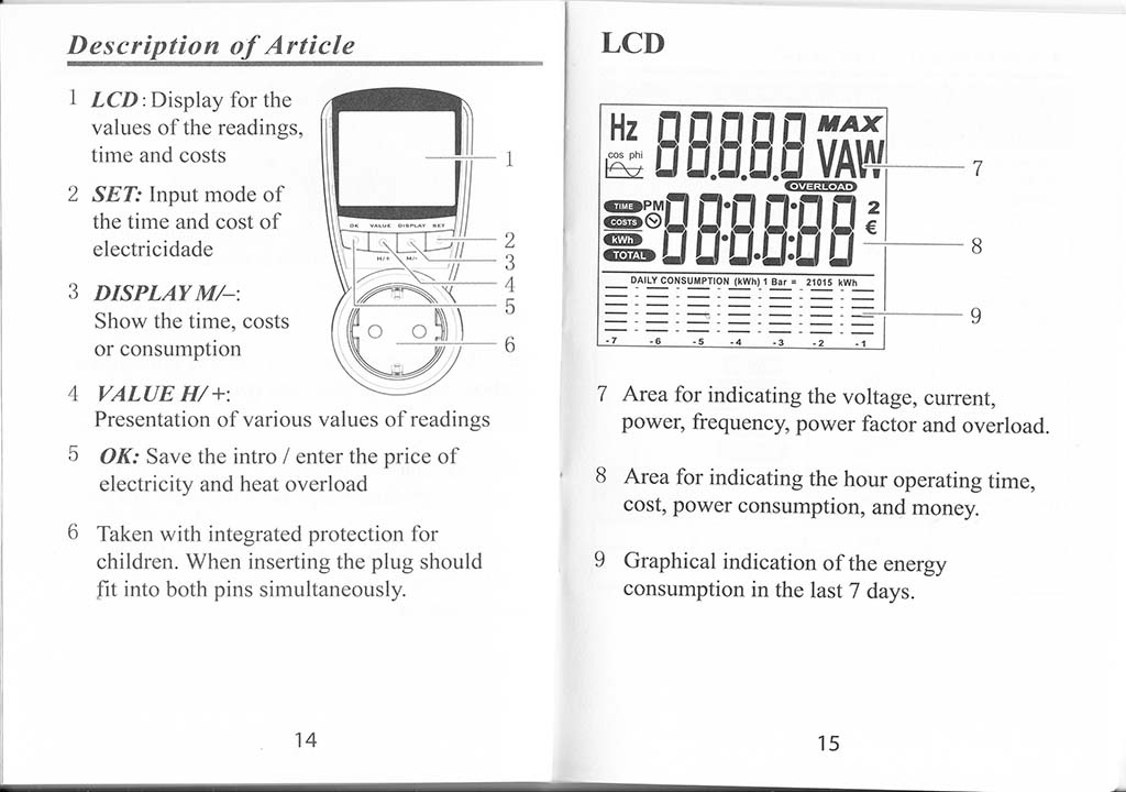
Description of Article
LCD. Display for the values of the readings, time and costs
SET: Input mode of the time and cost of electricidade
DISPLAY M/-: Show the time, costs or consumption
VALUE H/+: Presentation of various values of readings
OK: Save the intro / enter the price of electricity and heat overload
Taken with integrated protection for children. When inserting the plug should fit into both pins simultaneously.
Area for indicating the voltage, current, power, frequency, power factor and overload.
Area for indicating the hour operating time, cost, power consumption, and money.
Graphical indication of the energy consumption in the last 7 days.
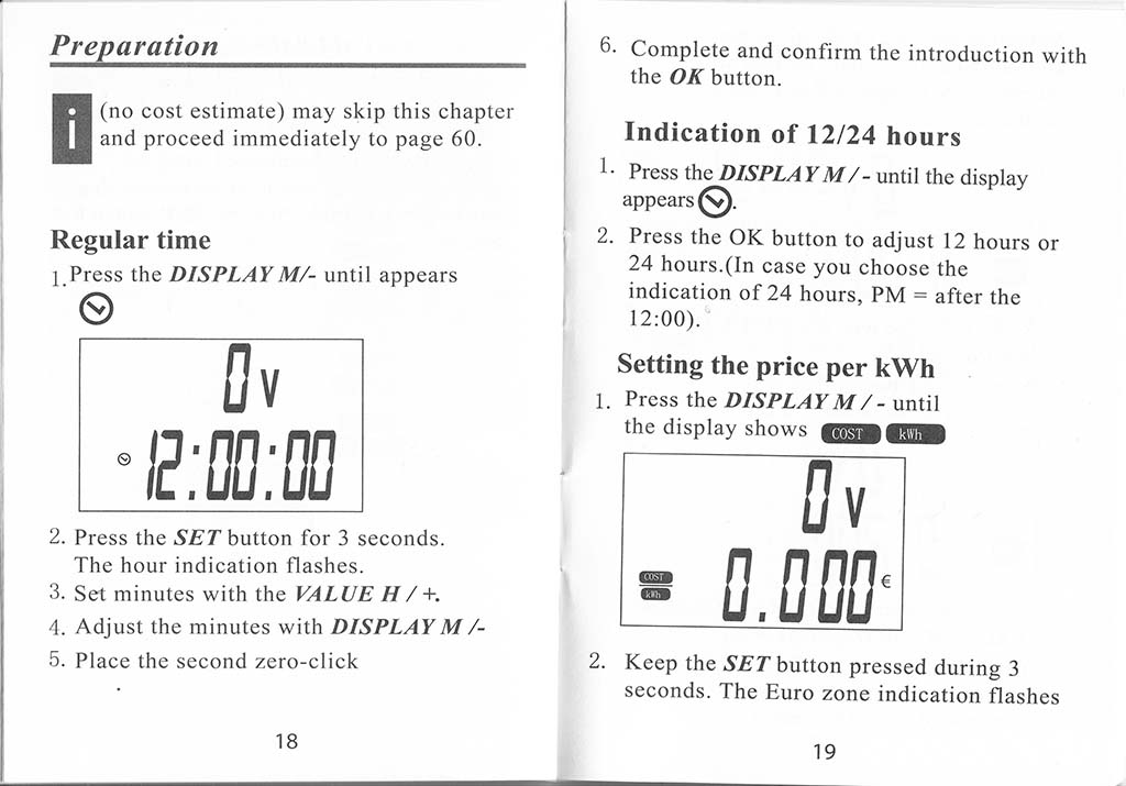
(no cost estimate) may skip this chapter and proceed immediately to page 60.
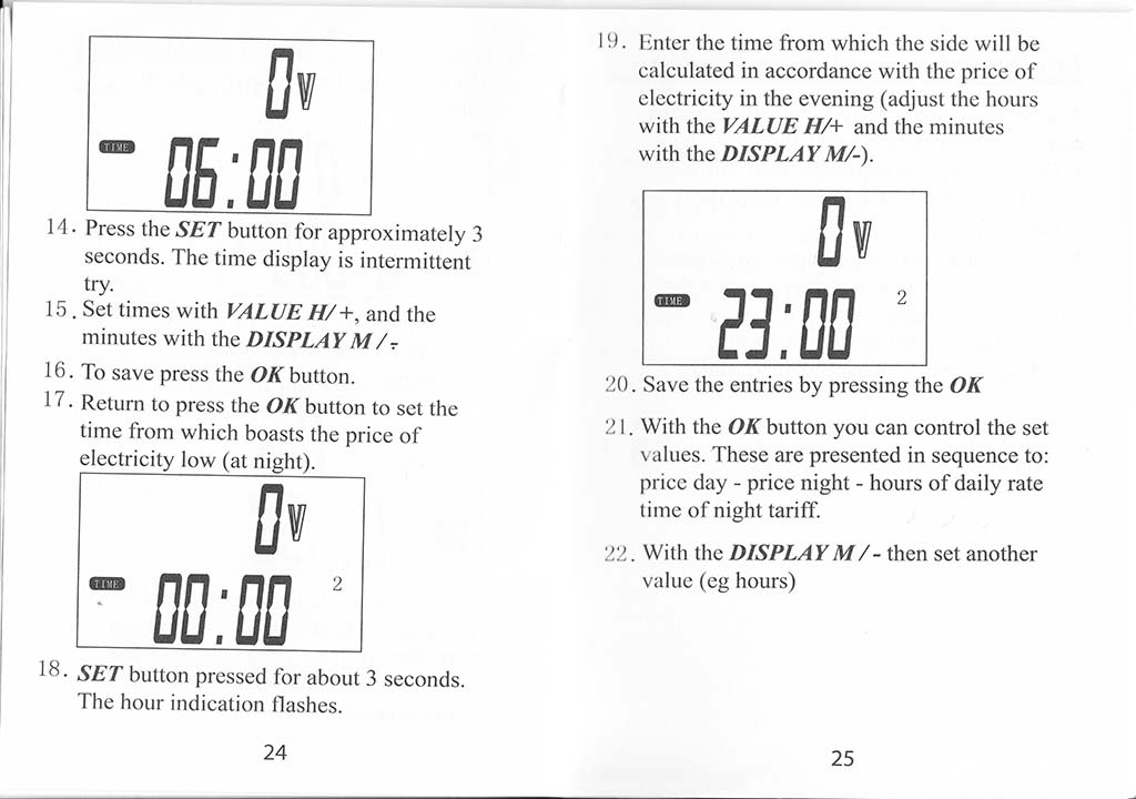
Regular time
l.Press the DISPLAYM/- until appears
2. Press the SET button for 3 seconds.
The hour indication flashes.
3. Set minutes with the VALUE H / +.
4. Adjust the minutes with DISPLAYM/-
5. Place the second zero-click
18
6. Complete and confirm the introduction with the OK button.
Indication of 12/24 hours
Press the DISPLA YM/- until the display appears
2. Press the OK button to adjust 12 hours or 24 hours.(In case you choose the indication of 24 hours, PM = after the 12:00).**
Setting the price per kWh 1. Press the DISPLAYM/- until the display shows aBSantM
2. Keep the SET button pressed during 3 seconds. The Euro zone indication flashes
19
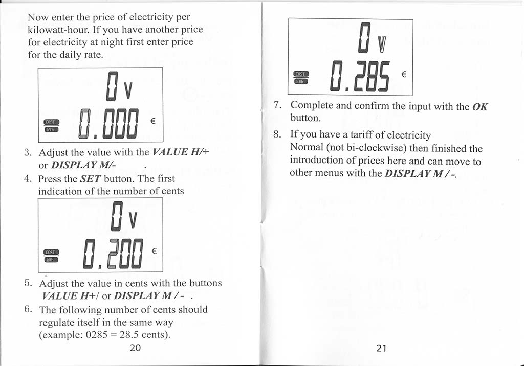
Now enter the price of electricity per kilowatt-hour. If you have another price for electricity at night first enter price for the daily rate.
Bv I
a O.flflfl ‘
3. Adjust the value with the VALUE H/+ or DISPLAY M/-
4. Press the SET button. The first indication of the number of cents
flv
* Q. POO
5. Adjust the value in cents with the buttons
VALUE H+/ or DISPLAYM/- .
6. The following number of cents should regulate itself in the same way (example: 0285 = 28.5 cents).
20
Hi
Complete and confirm the input with the OK button.
If you have a tariff of electricity Normal (not bi-clockwise) then finished the introduction of prices here and can move to other menus with the DISPLAYM/-.
21
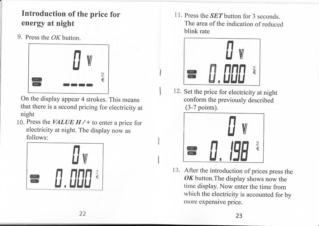
Introduction of the price for energy at night
9. Press the OK button.
On the display appear 4 strokes. This means that there is a second pricing for electricity at night
10. Press the VALVE H/+ to enter a price for electricity at night. The display now as follows:
22
11. Press the SET button for 3 seconds. The area of the indication of reduced blink rate
D V
Its cost of the electricity meter stores the energy consumption of the equipment connected over a period of past 7 days.
The LCD display shows a graphical presentation below, each column represents a day (-1 = Yesterday, = -7 a week ago).
DAILY CONSUMPTION (kWh) 1 Bar • 15 kWh
-7 -6 -5 -4 -3 -2 -1
The individual bars in the columns represent the kWh consumed.
According to consumption changes the scale, so that each bar corresponds to l, 2,5, 10 or 15 kWh.
29
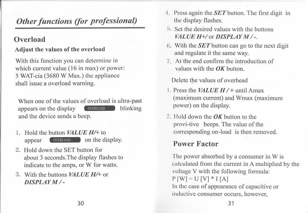
Other functions (for professional)
Overload
Adjust the values of the overload
With this function you can determine in which current value (16 in max) or power: 5 WAT-cia (3680 W Max.) the appliance shall issue a overload warning.
When one of the values of overload is ultra-past appears on the display dH2Z2!!^B blinking and the device sends a beep.
1.
Hold the button VALUE H/+ to
appear
OVERLOAD
on the display.
2. Hold down the SET button for
about 3 seconds.The display flashes to indicate to the amps, or W for watts.
3. With the buttons VALUE H/+ or DISPLAY M/-
30
4. Press again the SET button. The first digit in the display flashes.
5. Set the desired values with the buttons VALUE H+/ot DISPLAY M/-.
6. With the SET button can go to the next digit and regulate it the same way.
7. At the end confirm the introduction of values with the OK button.
Delete the values of overhead
1. Press the VALUE H/+ until Amax (maximum current) and Wmax (maximum power) on the display.
2. Mold down the OK button to the provi-tive beeps. The value of the corresponding on-load is then removed.
Power Factor
The power absorbed by a consumer in W is calculated from the current in A multiplied by the voltage V with the following formula:
P [W] = U [V] * I [A]
In the case of appearance of capacitive or inductive consumer occurs, however,
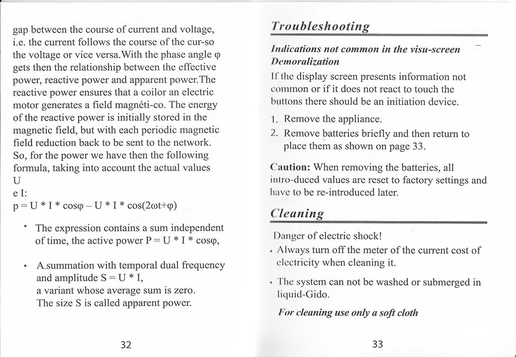
gap between the course of current and voltage, i.e. the current follows the course of the cur-so the voltage or vice versa. With the phase angle <p gets then the relationship between the effective power, reactive power and apparent power.The reactive power ensures that a coilor an electric motor generates a field magneti-co. The energy of the reactive power is initially stored in the magnetic field, but with each periodic magnetic field reduction back to be sent to the network. So, for the power we have then the following formula, taking into account the actual values U e I:
p = U * I * coscp – U * I * cos(2cot+tp)
* The expression contains a sum independent of time, the active power P = U * I * coscp,
• A.summation with temporal dual frequency and amplitude S = U * I,
a variant whose average sum is zero.
The size S is called apparent power.
Troubleshooting
Indications not common in the visu-screen Demoralization
If the display screen presents information not common or if it does not react to touch the buttons there should be an initiation device.
1. Remove the appliance.
2. Remove batteries briefly and then return to place them as shown on page 33.
Caution: When removing the batteries, all intro-duced values arc reset to factory settings and have to be re-introduced later.
Cleaning___________
Danger of electric shock!
• Always turn off the meter of the current cost of electricity when cleaning it.
• The system can not be washed or submerged in liquid-Gido.
For cleaning use only a soft doth
33
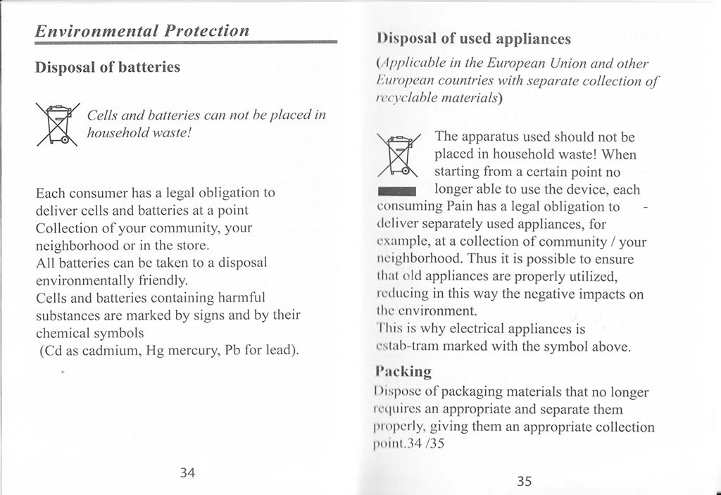
Environmental Protection
Disposal of batteries
Cells and batteries can not be placed in household waste!
Each consumer has a legal obligation to deliver cells and batteries at a point Collection of your community, your neighborhood or in the store.
All batteries can be taken to a disposal environmentally friendly.
Cells and batteries containing harmful substances are marked by signs and by their chemical symbols
(Cd as cadmium, Hg mercury, Pb for lead).
34
Disposal of used appliances
(Applicable in the European Union and other European countries with separate collection of recyclable materials)
The apparatus used should not be placed in household waste! When starting from a certain point no longer able to use the device, each consuming Pain has a legal obligation to deliver separately used appliances, for example, at a collection of community / your neighborhood. Thus it is possible to ensure that old appliances are properly utilized, reducing in this way the negative impacts on I he environment.
This is why electrical appliances is eslab-tram marked with the symbol above.
Packing
I )ispose of packaging materials that no longer requires an appropriate and separate them properly, giving them an appropriate collection poinl.34/35
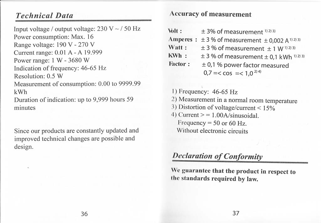
Technical Data
Input voltage / output voltage: 230 V ~ / 50 Hz
Power consumption: Max. 16
Range voltage: 190 V – 270 V
Current range: 0.01 A – A 19.999
Power range: 1 W – 3680 W
Indication of frequency: 46-65 Hz
Resolution: 0.5 W
Measurement of consumption: 0.00 to 9999.99 kWh
Duration of indication: up to 9,999 hours 59 minutes
Since our products are constantly updated and improved technical changes are possible and design.
Accuracy of measurement
V>lt: ± 3% of measurement,,a3,
Amperes : ± 3 % of measurement ±0,002 A1)2)3) Watt: ±3%ofmeasurement ±1 W”2131
KWh: ±3%ofmeasurement±0,1 kWh,,2)31
Factor: ± 0,1 % power factor measured
0,7 =< cos =<1,02)4>
1) Frequency: 46-65 Hz
2) Measurement in a normal room temperature
3) Distortion of voltage/current < 15%
4) Current > = 1.00A/sinusoidal.
Frequency = 50 or 60 Hz.
Without electronic circuits
Declaration of Conformity___________
We guarantee that the product in respect to the standards required by law.
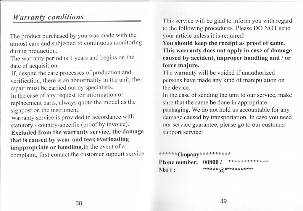
Warranty conditions
The product purchased by you was made with the utmost care and subjected to continuous monitoring during production.
The warranty period is 1 years and begins on the date of acquisition.
If, despite the care processes of production and verification, there is an abnormality in the unit, the repair must be carried out by specialists.
In the case of any request for information or replacement parts, always quote the model as the signpost on the instrument.
Warranty service is provided in accordance with statutory / country-specific (proof by invoice). Excluded from the warranty service, the damage that is caused by wear and teas overloading inappropriate or handling.in the event of a complaint, first contact the customer support service.
This service will be glad to inform you with regard to the following procedures. Please DO NOT send your article unless it is required!
You should keep the receipt as proof of same. This warranty does not apply in case of damage caused by accident, improper handling and / or force majure.
The warranty will be voided if unauthorized persons have made any kind of manipulation on the device.
In the case of sending the unit to our service, make sure that the same be done in appropriate packaging. We do not hold us accountable for any damage caused by transportation. In case you need Our service guarantee, please go to our customer support service:
******Q)|jp2|jy**********
Plume number 00800 / *************
j\ i |; *****(»*********
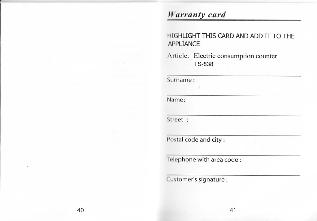
Warranty card
HIGHLIGHT THIS CARD AND ADD IT TO THE APPLIANCE
Article: Electric consumption counter TS-838
Surname:
Name:
Street :
Postal code and city:
1elephone with area code:
Customer’s signature:
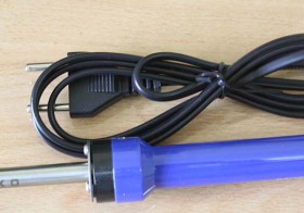
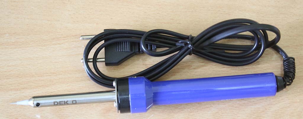
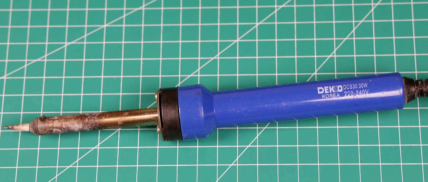
Mata soldernya runcing, cocok untuk menyolder komponen kecil seperti SMD
Mata solder Dekko DCS30 (close up)
Mata solder Dekko DCS30
Manual Dekko DCS30 terdapat di karton kemasannya
Kemasan Dekko DCS30 bagian luar
Kemasan Dekko DCS30 bagian dalam, berisi manual dua bahasa
Manual bahasa Inggris
WATTAGE AND APPLICATION
20 40W
60 80W
Above 100W
P.C. BoardI.C. Transistor
Chip Conden&or
Electric PartsSwitch, Connector
Transformer
When a large heat capacity is required
HOW TO SOLDER
Clean the parts to be joined.
Clean soldering iron tip and tin all faces of tip with a coating of solder.
Heat parts (not solder) to be joined.
Apply flux core solder to heated parts, not the soldering tip, and heat it till solder melts and flow freely. ‘
Don t apply too much solder unnecessarily.
CAUTION
When the power is on, the tip temperature can reach over 300°C CS72°F). Since mishandling may lead to burns or fire, be sure to comply with the following precautions.
Do not touch the tip and the metalic parts near the tip.
Do not use the product near flammable items. Unplug when the unit is not in use.
Do not warm up the soldering iron with the tip pointing down.
Do not use the unit for applications other than soldering.
Do not wet the unit or use the unit when your hands are wet.
Do not modify the unit. Use only genuine DEKKO replacement parts.
Do not shock the unit, or otherwise subject the heating element to severe damage.
The soldering process will produce smoke, so make sure the area is well ventilated.
Children should be supervised to ensure that they do not play with the DEKKO.
WARNING
In order to avoid burns, do not attempt to touch except grip as the unit is hot. And do not leave the unit unattended.
Do not attempt to use the unitaround combustible in order to prevent tires.
Diatas 100W: Bila diperlukan Kapasitas panas besar
CARA MENYODER
Bersihkan bagian yang disolder.
Bersihkan ujung solder dan lapisi ujung solder dengan timah.
Panaskan bagian untuk disolder.
Beri timah pada bagian yang telah dipanaskan, bukan ujung solder, panaskan sampai cair dan rata.
Jangan beri terlalu banyak timah.
PERHATIAN
Ketika solder on, ujung solder bisa mencapai temperatur lebih dari 300°C (572*F). Penanganan
yang salah bisa menyebabkan luka bakar dan kebakaran, perhatikan hal-hal berikut:
Jangan sentuh ujung dan bagian metal dekat ujung.
Jangan digunakan dekat bahan yang mudah terbakar cabut ketika tidak dipakai.
Hadapkan ujung solder ke atas <waktu pemanasan.
Jangan dipakai selain untuk menyoder.
Jangan sampai alat basah atau tangan basah.
Jangan memodifikasi alat solder. Pakai pengganti DEKKOyang asli.
Jangan menggoncang alat solder, bisa menyebabkan elemen pemanas rusak.
Proses penyoderan mengeluarkan asap, pastikan ventjlasi ruangan memadai.
Jauhkan alat DEKKO dari anak-anak.
PERINGATAN
Untuk mencegah luka bakar, jangan menyentuh alat solder yang sendang panas. Dan jangan membiarkan alat solder tanpa terjaga.
Jangan memakai alat solder di lingkurigan yang mudah terbakar untuk menghindari kebakaran
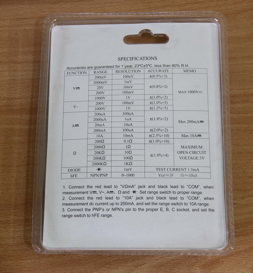
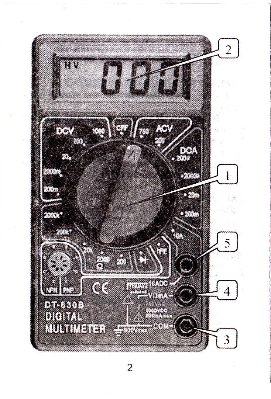
Penampakan bagian belakang kemasan. Di situ tercantum spesifikasi digital multimeter tersebut.
Kemasan bagian belakang
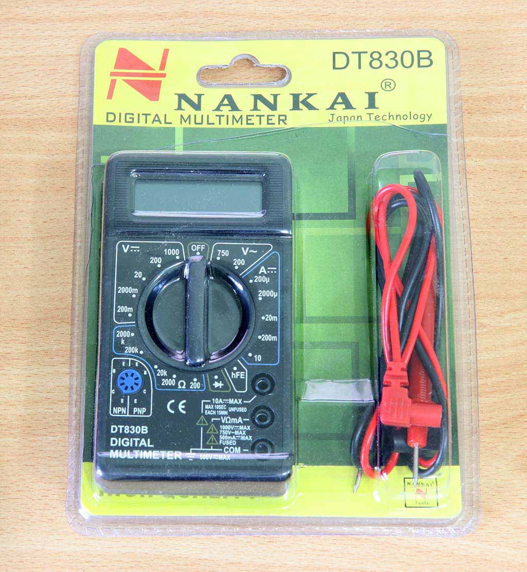
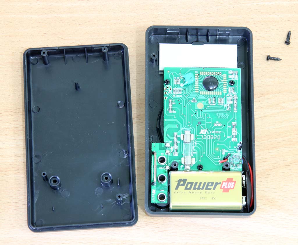
Bagian dalam multimeter DT830B
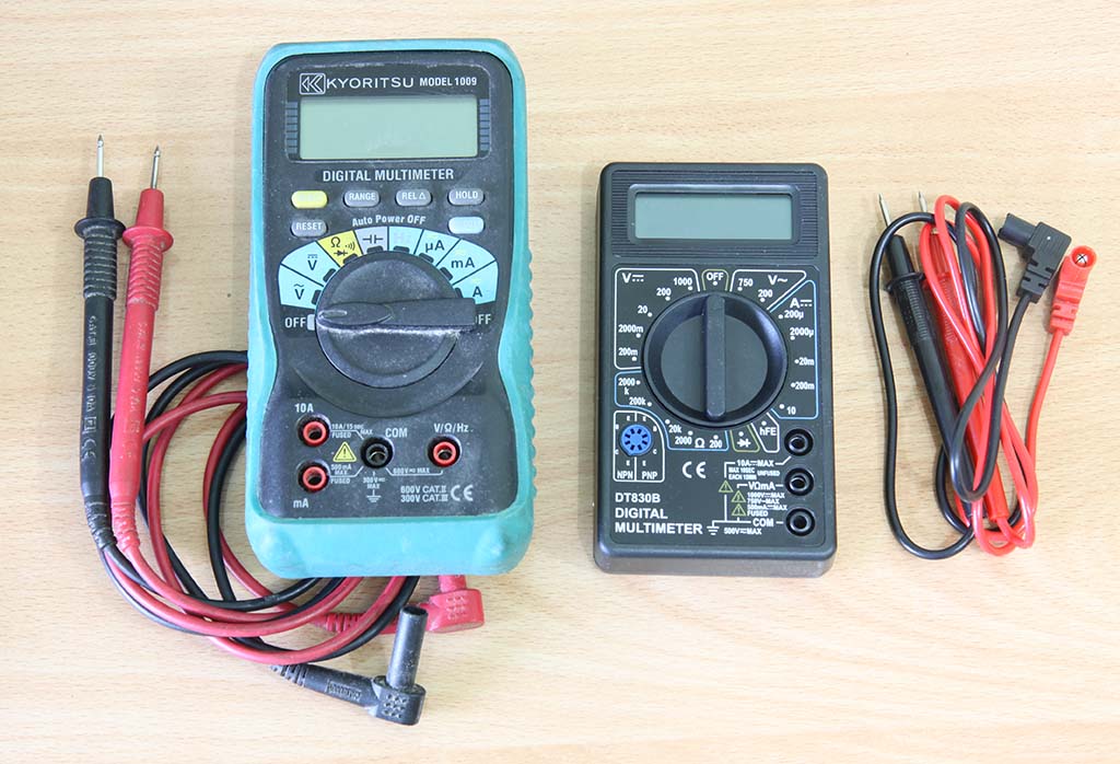
Perbandingan fisik digital multimeter Nankai DT830B dengan Kyoritsu model 1009
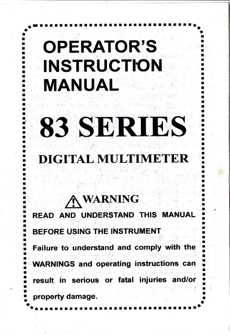
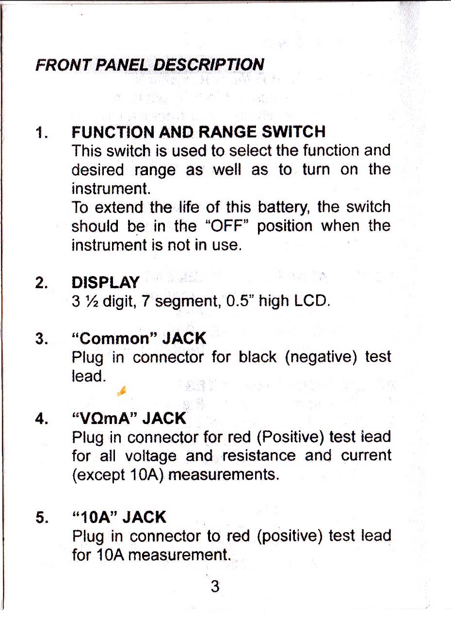
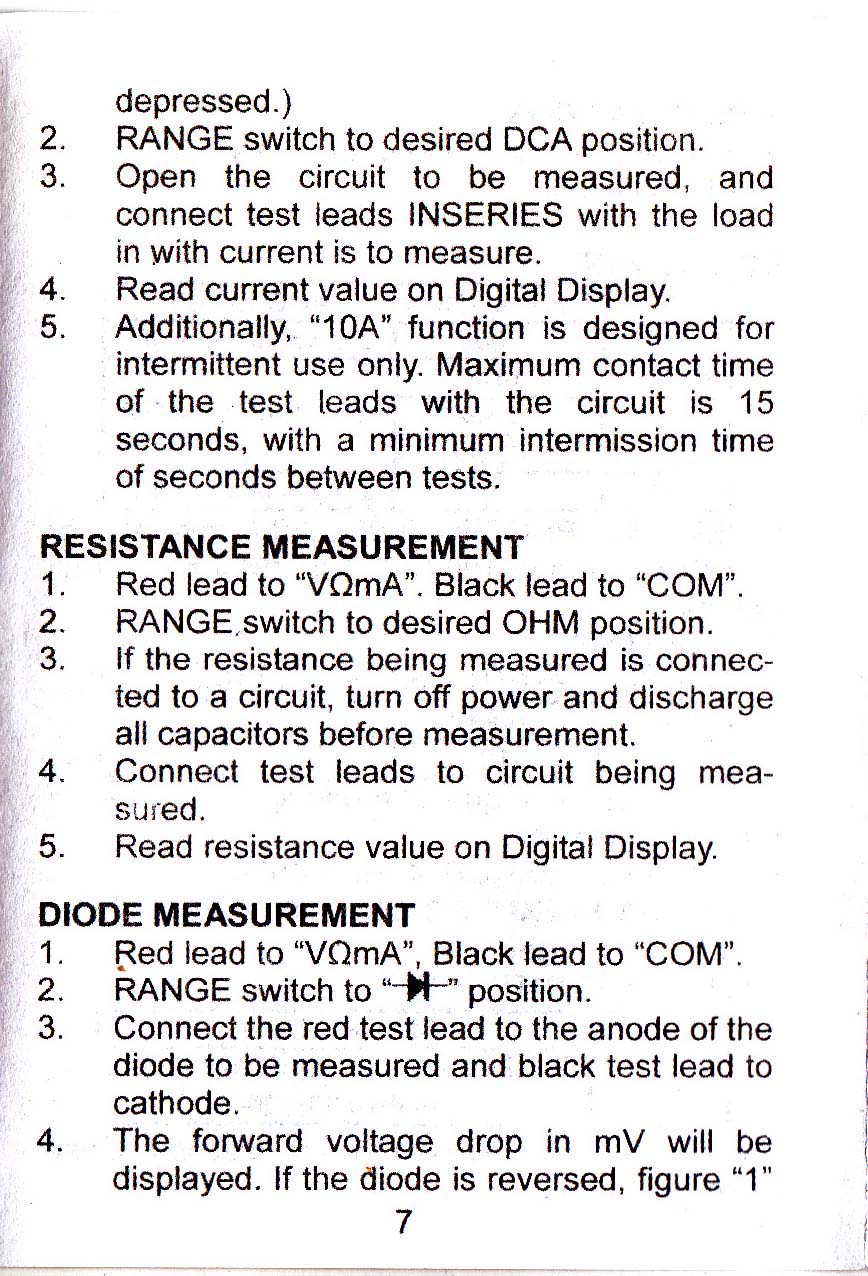
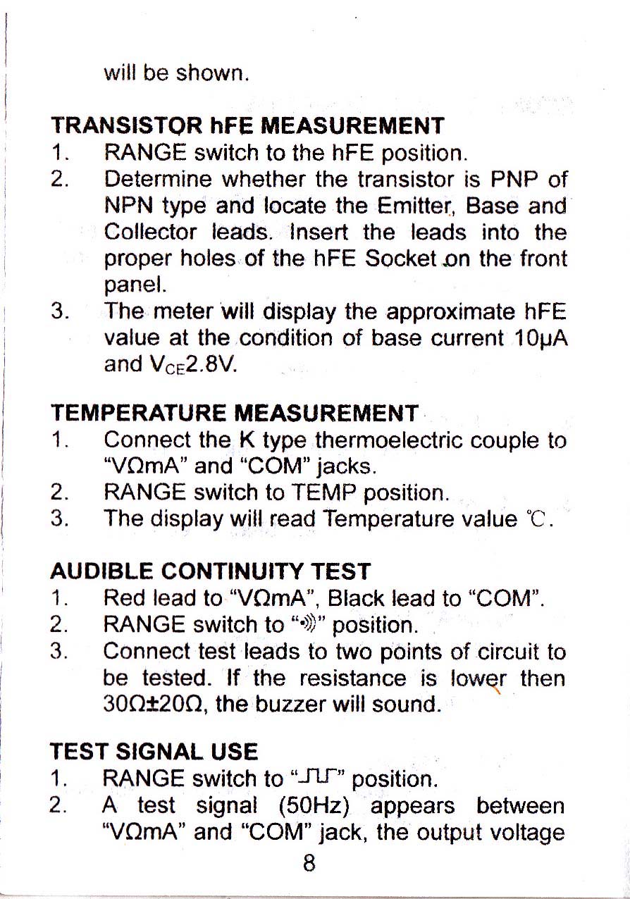
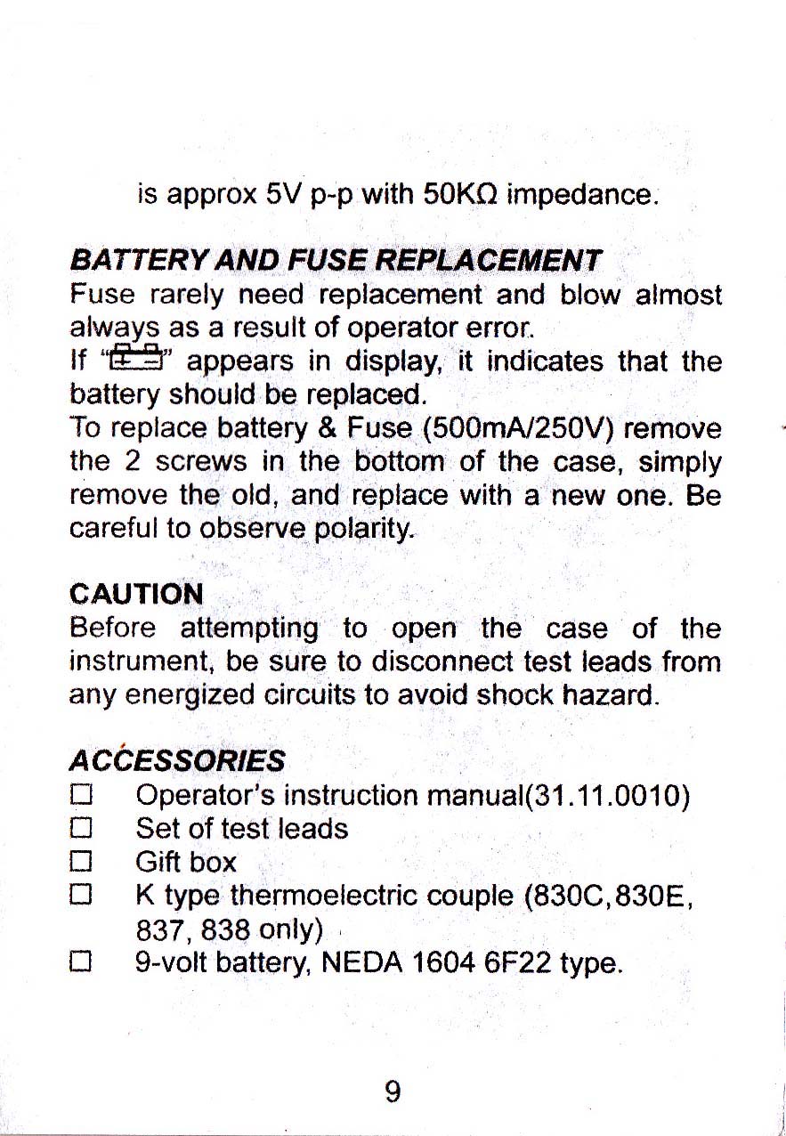
Manual DT830B
Berikut ini manual untuk DT830B
Manual DT830B – Cover
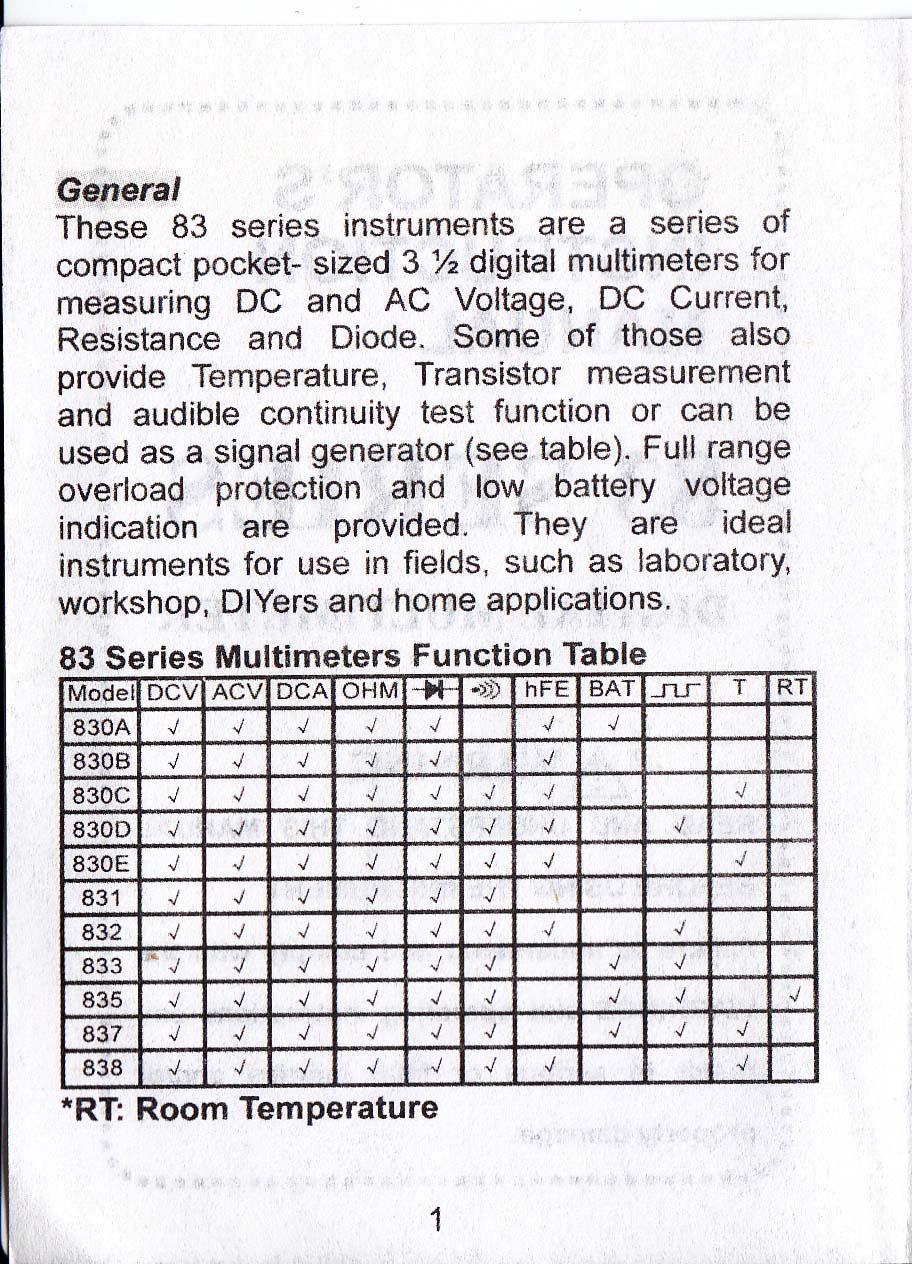
DT830B manual halaman 1
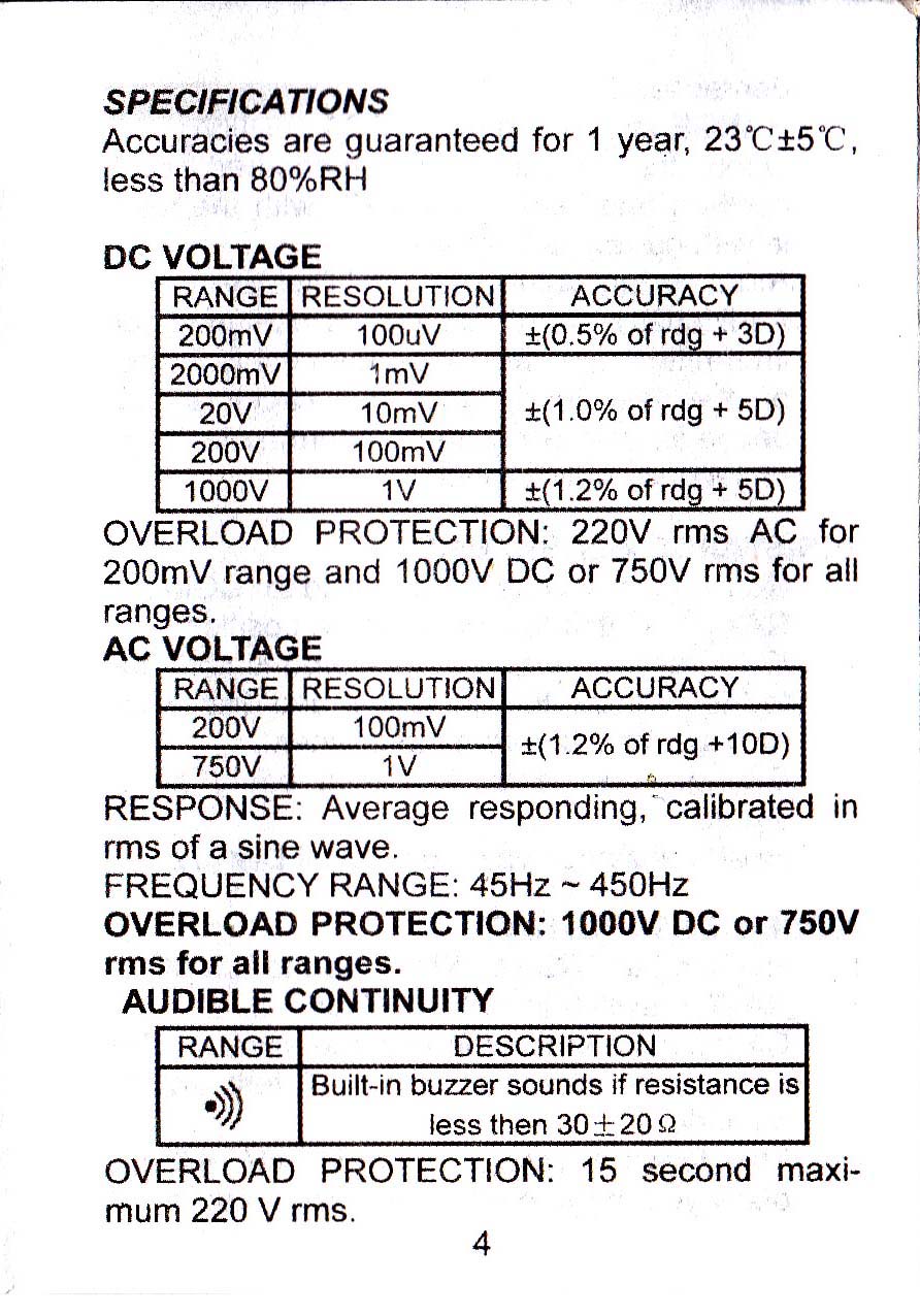
Manual DT830B halaman 2
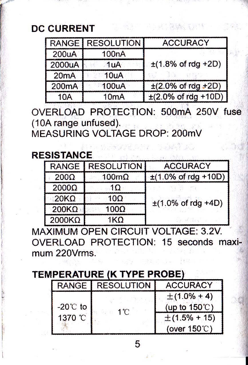
DT830b manual halaman 3
DT830B manual halaman 4
DT830B manual halaman 5
DT830b manual halaman 6
DT830B manual halaman 7
DT830B manual halaman 8
DT830B manual halaman 9
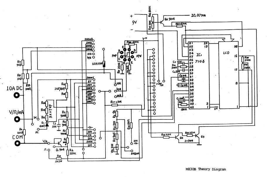
Skema rangkaian DT830B menurut http://www.hobby-hour.com/electronics/dt830b-digital-multimeter.https://elektrologi.iptek.web.id
Skema rangkaian DT830B
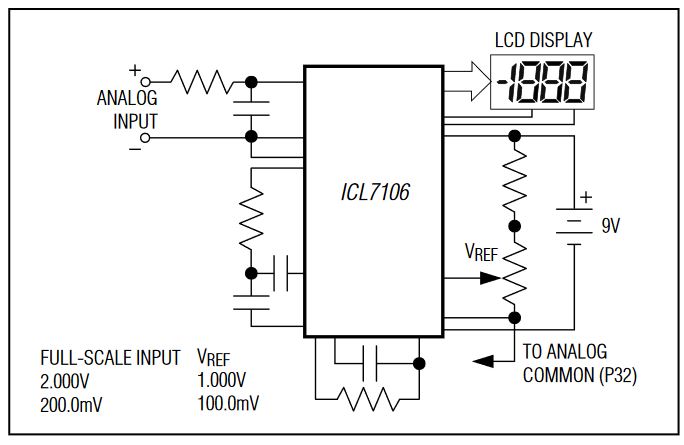
Komponen utama multimeter tersebut adalah IC tipe “ICL7106 3 1/2 Digit A/D Converter” . Fungsi IC ini adalah mengubah tegangan analog menjadi angka digital, dan menampilkannya di sebuah display LCD (Liquid Crystal Display). Datasheet ICL7106 dapat dilihat di situs web Maxim Integrated (https://datasheets.maximintegrated.com/en/ds/ICL7106-ICL7107.pdf)
Berikut ini diagram sederhana ICL7106
Rangkaian sederhana ICL7106
Fungsi komponen-komponen lain adalah mengubah besaran listrik (arus, tegangan, resistansi) menjadi tegangan yang dapat dibaca oleh ICL7106.
Untuk merakit rangkaian elektronika, diperlukan beberapa alat bantu. Berikut ini beberapa alat bantu yang sering dipakai:
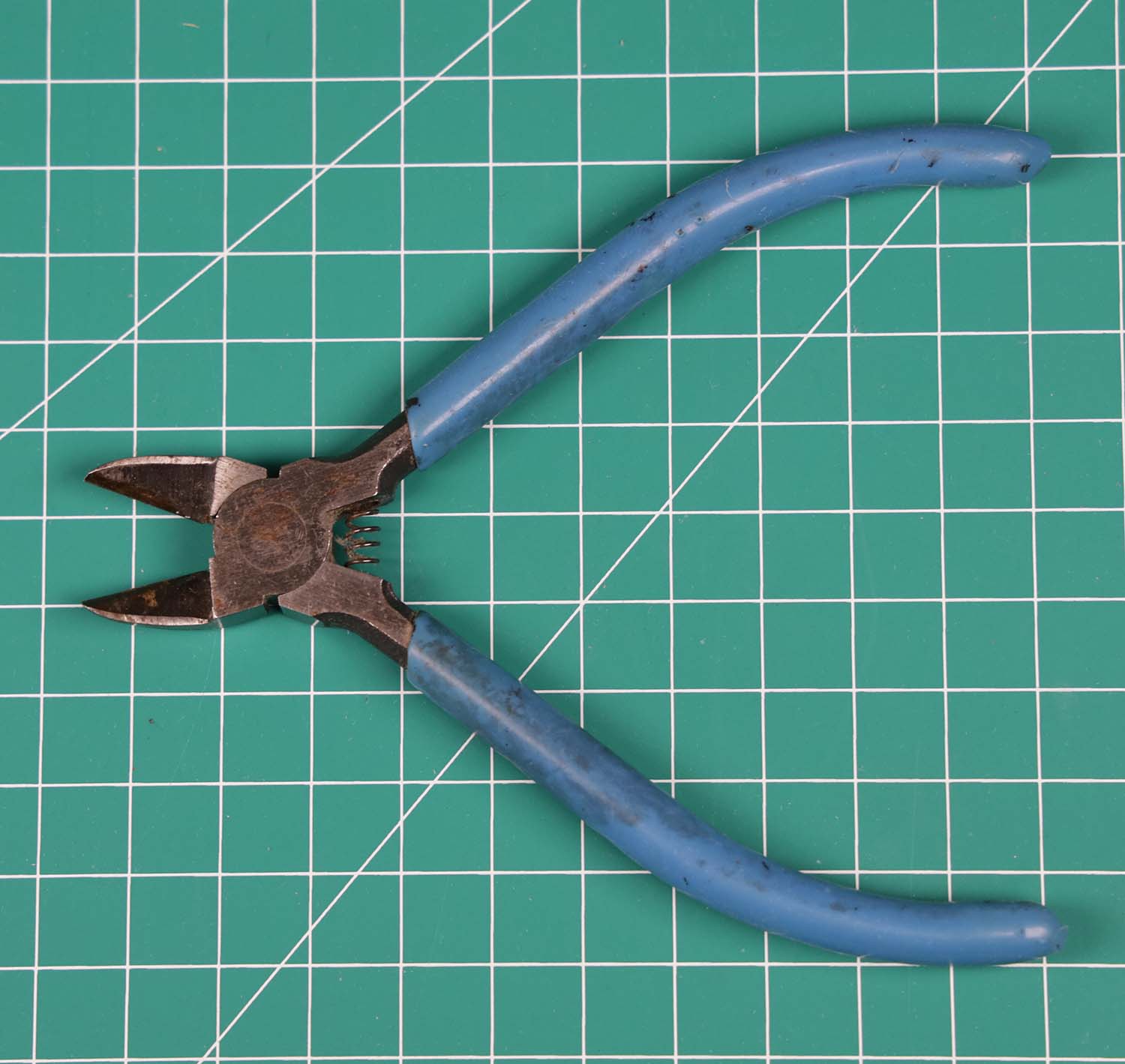
Tang Potong Kabel
Tang potong, untuk memotong kabel
Tang potong kabel biasanya hanya dapat dipakai untuk memotong kabel tembaga atau kabel lain yang lunak. Jangan dipakai untuk memotong kawat besi atau stainless steel yang keras.
Tang potong kabel
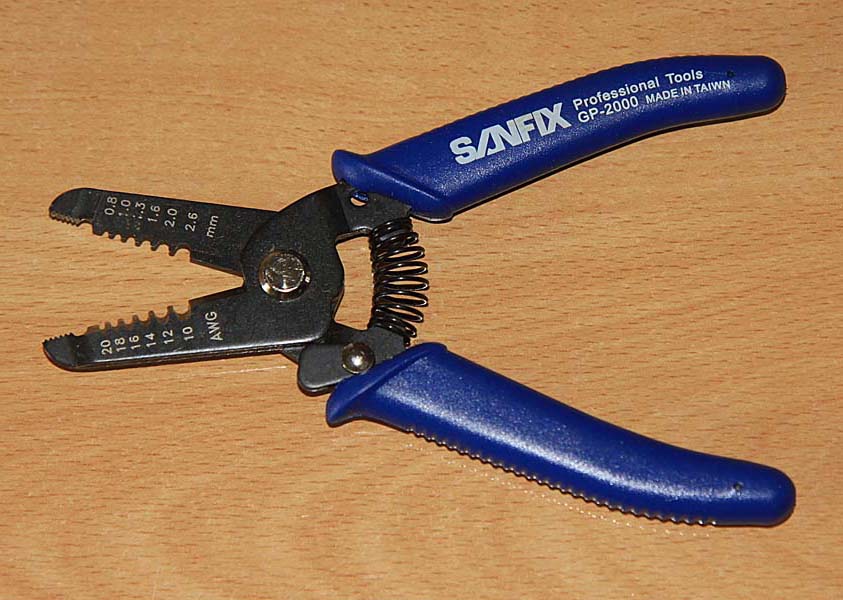
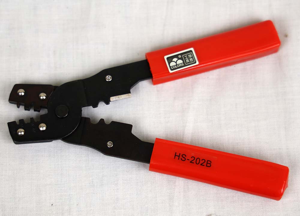
Tang Pengupas Kabel
Fungsinya untuk mengupas isolator kabel. Bisa juga pakai cutter/pisau, namun lambat dan kadang konduktor dalamnya ikut terpotong
Berikut ini tang pengupas kabel Sanfix GP2000, sederhana dan murah, cocoknya untuk kabel yang agak besar, namun kurang cocok untuk mengupas kabel yang kecil
Tang pengupas kabel Sanfix GP-2000
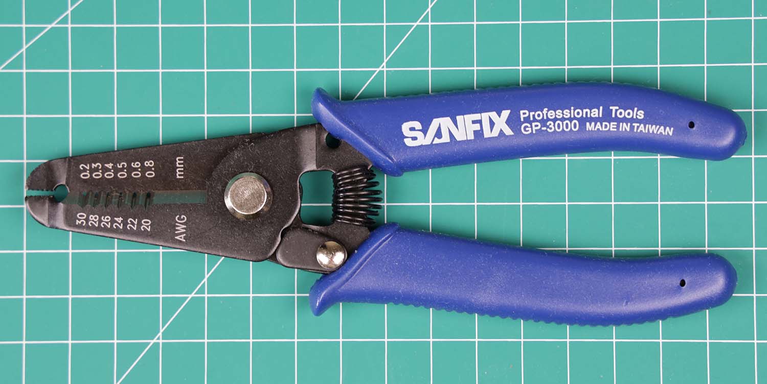
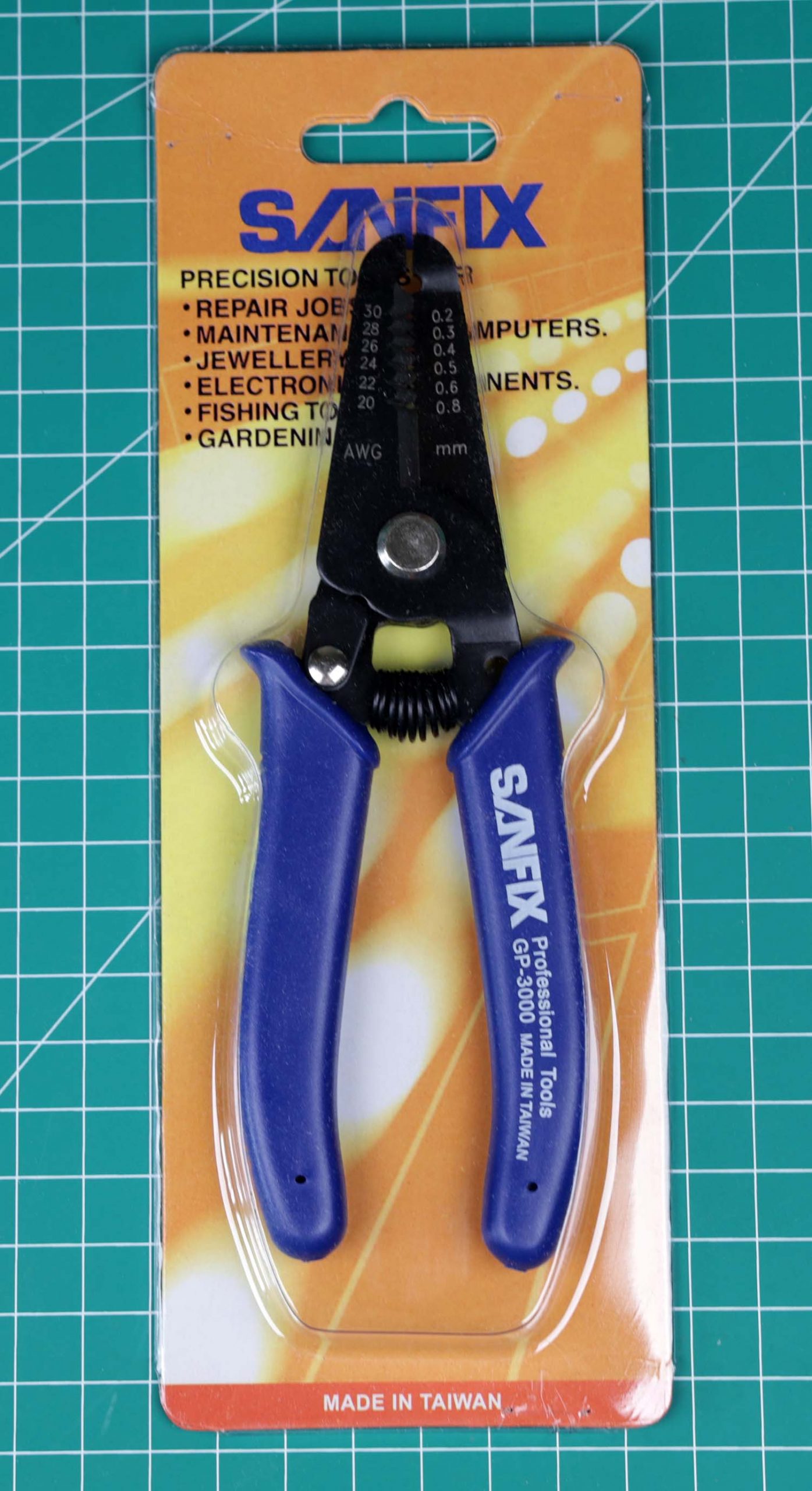
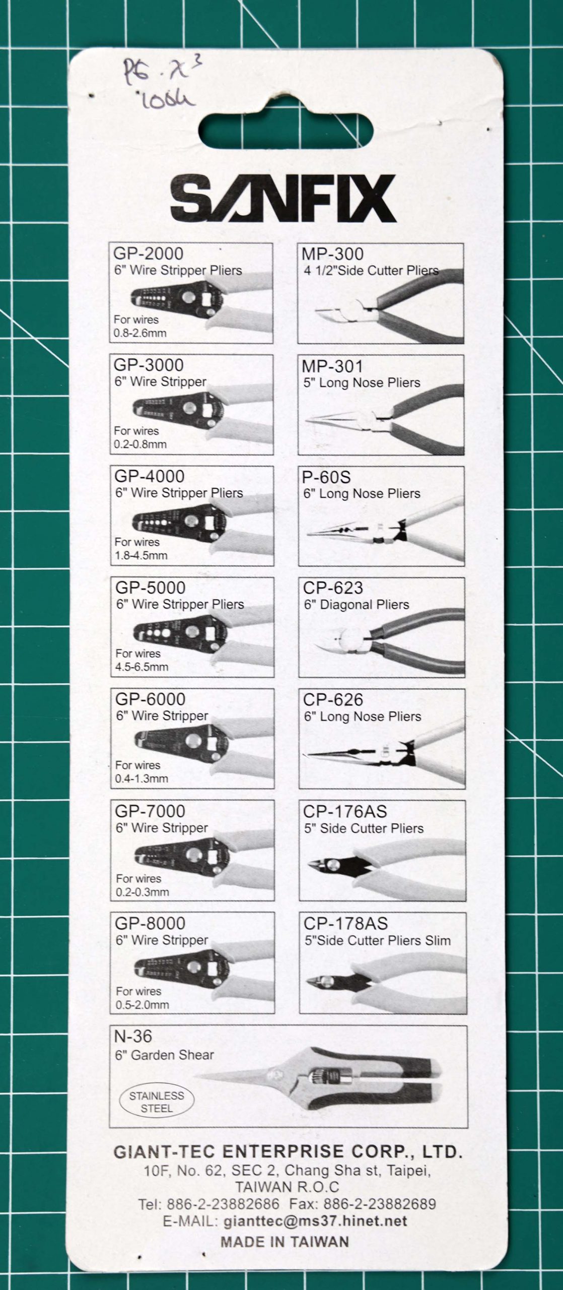
Untuk mengupas kabel yang lebih kecil, dapat menggunakan tang pengupas kabel Sanfix GP-3000
Tang pengupas kabel Sanfix GP-3000
Tang pengupas kabel ada juga yang dilengkapi dengan mekanisme pengungkit, sehingga isolator yang telah dikupas dapat otomatis ditarik oleh tang tersebut. Namun tang seperti ini harganya lumayan mahal dan perlu setting yang tepat supaya dapat mengupas kabel dengan baik.
Tang pengupas kabel Goot
Berikut ini tang pengupas Dekko yang juga dilengkapi mekanisme pengungkit untuk menarik isolator sampai lepas.
Tang pengupas kabel merek Dekko
Tang Lancip
Tang lancip dengan ujung kecil sering dipakai untuk membengkokkan kaki komponen sebelum dipasang ke PCB.
Tang lancip
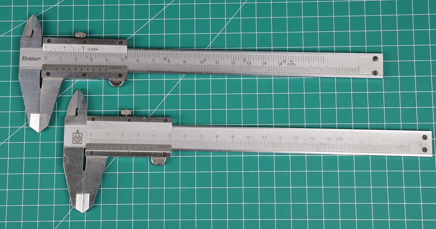
Jangka Sorong
Jangka sorong penting pada proses perancangan PCB, untuk mengukur komponen yang dipakai agar ukurannya sesuai dengan lubang di PCB.