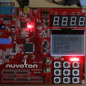
Alokasi PIN GPIO adalah sebagai berikut:
| Pin | Function |
| GPA0 | Key Matrix |
| GPA1 | Key Matrix |
| GPA2 | Key Matrix |
| GPA3 | Key Matrix |
| GPA4 | Key Matrix |
| GPA5 | Key Matrix |
| GPA6 | |
| GPA7 | ADC Interface ke potensiometer on board |
| GPA8 | I2C0 SDA ke codec |
| GPA9 | I2C0 SCL ke codec |
| GPA10 | I2C1 SDA ke EEPROM |
| GPA11 | I2C1 SCL ke EEPROM |
| GPA12 | RGB LED |
| GPA13 | RGB LED |
| GPA14 | RGB LED |
| GPA15 | I2SMCLK ke codec |
| GPB0 | UART0 Rx |
| GPB1 | UART0 Tx |
| GPB2 | |
| GPB3 | |
| GPB4 | UART1 Rx ke LIN |
| GPB5 | UART1 Tx ke LIN |
| GPB6 | LIN transceiver wakeup function |
| GPB7 | LIN transceiver Enable Disable |
| GPB8 | |
| GPB9 | |
| GPB10 | |
| GPB11 | Buzzer on board |
| GPB12 | CAN transceiver speed |
| GPB13 | CAN transceiver speed |
| GPB14 | |
| GPB15 | INT0, disambung ke SW_INT |
| GPC0 | I2SLRCLK ke Codec |
| GPC1 | I2SBCLK ke codec |
| GPC2 | I2SDI ke codec |
| GPC3 | I2SDO ke codec |
| GPC4 | LED 7 Segment Column |
| GPC5 | LED 7 Segment Column |
| GPC6 | LED 7 Segment Column |
| GPC7 | LED 7 Segment Column |
| GPC8 | SD interface ke SD Card Interface |
| GPC9 | SD interface ke SD Card Interface |
| GPC10 | SD interface ke SD Card Interface |
| GPC11 | SD interface ke SD Card Interface |
| GPC12 | LED ke (LED5~8) |
| GPC13 | LED ke (LED5~8) |
| GPC14 | LED ke (LED5~8) |
| GPC15 | LED ke (LED5~8) |
| GPD0 | SPI2 ke Flash |
| GPD1 | SPI2 ke Flash |
| GPD2 | SPI2 ke Flash |
| GPD3 | SPI2 ke Flash |
| GPD4 | SPI2 ke Flash |
| GPD5 | SPI2 ke Flash |
| GPD6 | CAN0 Rx ke modul CAN |
| GPD7 | CAN0 Tx ke modul CAN |
| GPD8 | SPI3 ke LCD Panel |
| GPD9 | SPI3 ke LCD Panel |
| GPD10 | SPI3 ke LCD Panel |
| GPD11 | SPI3 ke LCD Panel |
| GPD12 | SD power ke SD Card Interface |
| GPD13 | SD detect ke SD Card Interface |
| GPD14 | Backlight LCD Panel |
| GPD15 | |
| GPE0 | LED 7 Segment ROW |
| GPE1 | LED 7 Segment ROW |
| GPE2 | LED 7 Segment ROW |
| GPE3 | LED 7 Segment ROW |
| GPE4 | LED 7 Segment ROW |
| GPE5 | LED 7 Segment ROW |
| GPE6 | LED 7 Segment ROW |
| GPE7 | LED 7 Segment ROW |
| GPE8 | |
| GPE9 | |
| GPE10 | |
| GPE11 | |
| GPE12 | |
| GPE13 | |
| GPE14 | Line out Enable/Disable ke codec |
| GPE15 | Line in plug in/out detect ke codec |
Selain pin GPIO, pada learning board tersebut ada juga pin lain sebagai berikut:
- PS2DAT ke konektor PS1
- PS2CLK ke konektor PS1
- ICEDAT ke modul In Circuit Emulator
- ICECLK ke modul In Circuit Emulator

